


Understanding Inductor Transient Response: Energy, Current, and Voltage Dynamics
Inductors store energy in a magnetic field generated by current flow, the direct opposite of capacitors, which store energy in an electric field created by voltage across two plates. This magnetic storage causes an inductor to resist changes in current, whereas a capacitor resists changes in voltage.
When an inductor is initially unenergised—no magnetic field and zero current—applying a voltage source makes it behave like an open circuit. It attempts to keep the current at zero, so the full source voltage appears across its terminals.
As time progresses, the inductor’s current rises toward the maximum value allowed by the circuit, and the voltage across its terminals falls correspondingly. Once the terminal voltage approaches zero (ideal case), the inductor essentially becomes a short circuit, conducting the full current with negligible voltage drop.
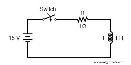
When the switch is first closed, the inductor voltage instantly equals the battery voltage, as the inductor behaves like an open circuit. Over time this voltage decays toward zero, while the current climbs toward its steady‑state value. The inductor voltage is found by subtracting the resistor’s voltage drop (I·R) from the battery voltage.
In a series R‑L circuit with a 15 V battery and a 1 Ω resistor, the current starts at 0 A and asymptotically approaches 15 A. The following table demonstrates the time‑dependent behavior using real values:
| Time (s) | Battery Voltage (V) | Inductor Voltage (V) | Current (A) |
|---|---|---|---|
| 0 | 15 | 15 | 0 |
| 0.5 | 15 | 9.098 | 5.902 |
| 1 | 15 | 5.518 | 9.482 |
| 2 | 15 | 2.030 | 12.97 |
| 3 | 15 | 0.747 | 14.25 |
| 4 | 15 | 0.275 | 14.73 |
| 5 | 15 | 0.101 | 14.90 |
| 6 | 15 | 37.181 mV | 14.96 |
| 10 | 15 | 0.681 mV | 14.99 |
Like the RC case, the inductor voltage decays asymptotically to zero while the current rises asymptotically to 15 A. For practical purposes, the voltage can be considered zero and the current effectively at its maximum after a few time constants.
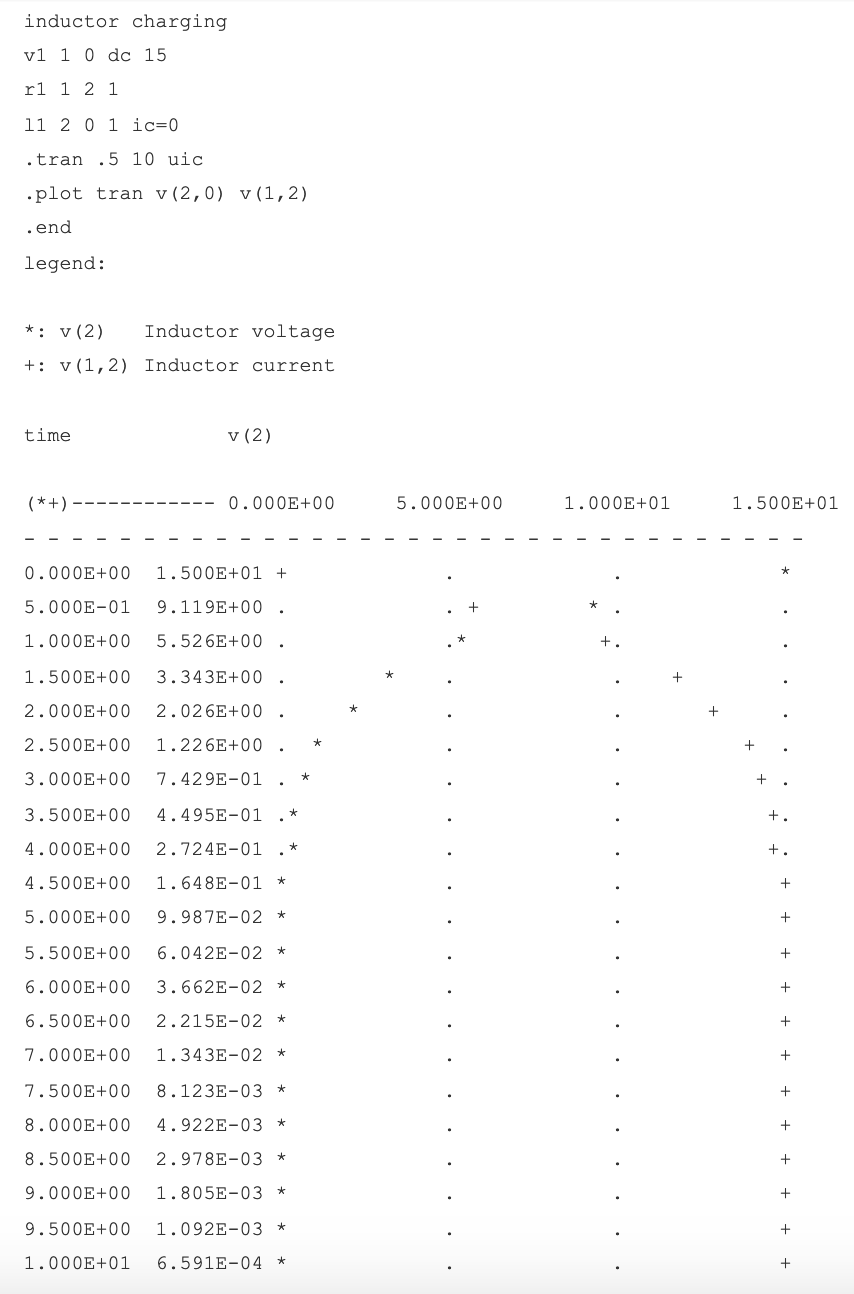
Using SPICE, the transient response can be visualised more clearly. The following plot shows the rapid initial drop in voltage and the corresponding rise in current, which then level off as time progresses.
Review:
- A completely unenergised inductor initially acts as an open circuit, then transitions to a short circuit once fully energised.
- In an R‑L charging circuit, the inductor current increases from zero to its final value while the voltage decreases from maximum to zero, with the most rapid changes occurring first and slowing toward the asymptote.
Related Worksheets:
- Time Constant Circuits Worksheet
- Time Constant Calculations Worksheet
Industrial Technology
- Using Commutating Diodes to Protect Inductive Loads
- Voltage‑to‑Current Signal Conversion: A Practical Transconductance Amplifier Design
- Understanding Voltage and Current: The Foundations of Electrical Flow
- Understanding Insulator Breakdown Voltage and Dielectric Strength
- Capacitors & Calculus: How Voltage Change Drives Current
- Inductors & Calculus: How Current Change Drives Voltage
- Understanding Capacitor Transient Response: Charging Dynamics, Asymptotic Behavior, and SPICE Simulation
- Understanding AC Inductor Circuits: Reactance, Phase Shift, and Power Dynamics
- AC Capacitor Circuits: Capacitive Reactance, Phase Shift, and Power Behavior
- Understanding Characteristic Impedance in Transmission Lines