


Understanding Capacitor Transient Response: Charging Dynamics, Asymptotic Behavior, and SPICE Simulation
Capacitors store electrical energy in an electric field, functioning much like miniature secondary‑cell batteries. A fully discharged capacitor exhibits zero volts across its terminals, while a charged capacitor maintains a steady voltage, mirroring a battery’s behavior.
When connected to an external voltage source, a capacitor absorbs energy and begins to charge. With a terminal voltage of zero, it initially behaves as a short circuit, drawing the maximum possible current until its voltage rises to match the source.
As the capacitor charges, its terminal voltage increases toward the applied voltage, and the current through the circuit diminishes proportionally. Once the capacitor’s voltage equals the source voltage, it effectively becomes an open circuit, drawing no further current.
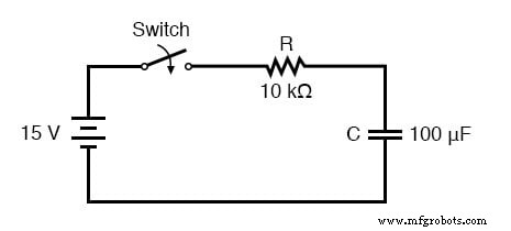
In a practical example, a 10 kΩ resistor is used to charge a 15 V battery. The table below illustrates the capacitor voltage and current over time:
| Time (s) | Battery Voltage | Capacitor Voltage | Current |
|---|---|---|---|
| 0 | 15 V | 0 V | 1500 µA |
| 0.5 | 15 V | 5.902 V | 909.8 µA |
| 1 | 15 V | 9.482 V | 551.8 µA |
| 2 | 15 V | 12.970 V | 203.0 µA |
| 3 | 15 V | 14.253 V | 74.68 µA |
| 4 | 15 V | 14.725 V | 27.47 µA |
| 5 | 15 V | 14.899 V | 10.11 µA |
| 6 | 15 V | 14.963 V | 3.718 µA |
| 10 | 15 V | 14.999 V | 0.068 µA |
Mathematically, this behavior is described as asymptotic: the capacitor voltage approaches the battery voltage and the current approaches zero, getting progressively closer over time but never exactly reaching the final state in theory. In practice, the capacitor reaches 15 V and the current effectively becomes zero.
Using the SPICE circuit analysis tool, the transient response can be visualized graphically. The following plot demonstrates the rapid initial rise of voltage and the gradual decay of current, with time on the vertical axis and amplitude on the horizontal axis:
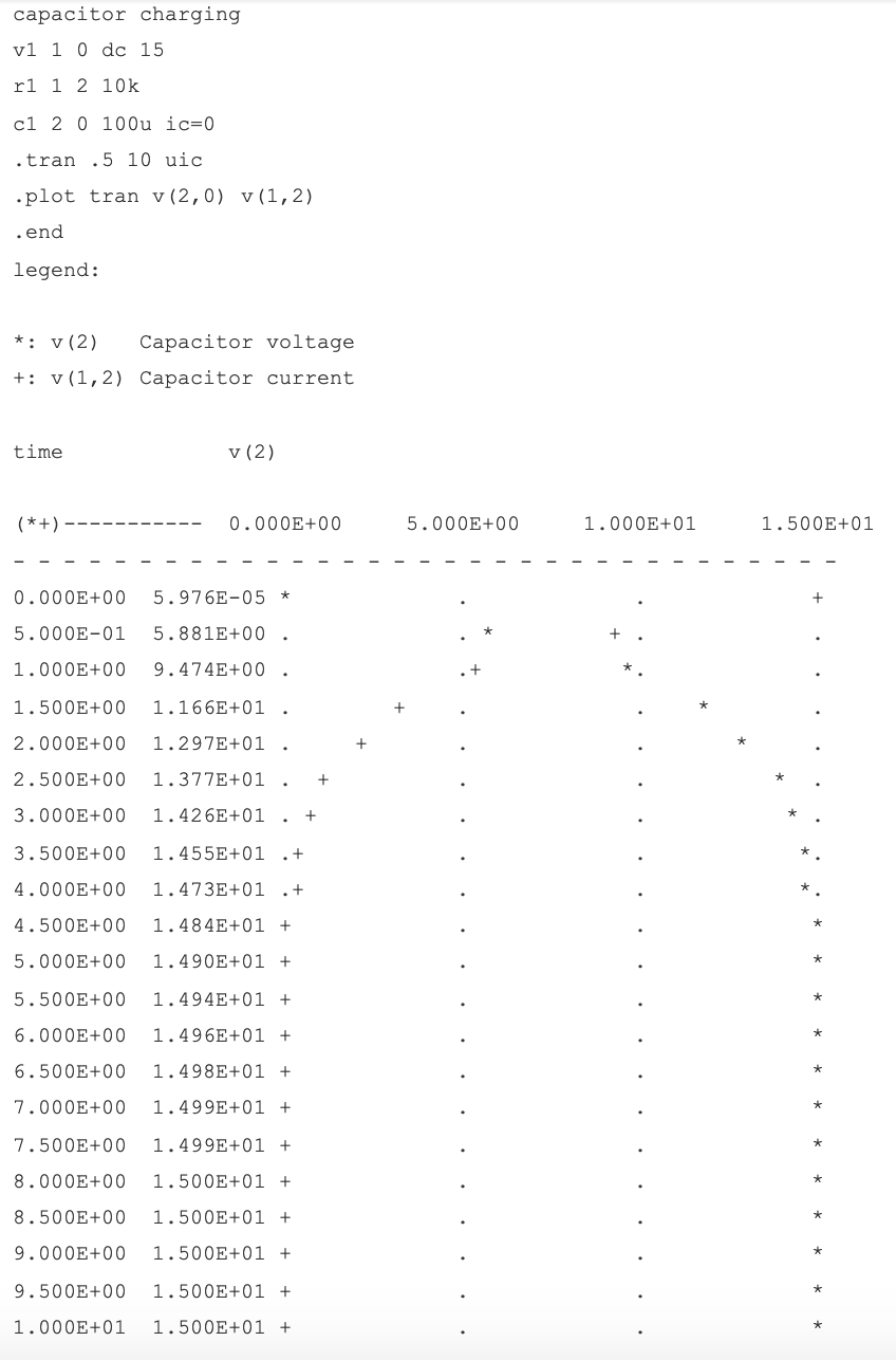
In the netlist, the .plot command is employed instead of the more common .print to generate a pseudo‑graphic plot directly in the terminal. The resistor serves as a shunt to measure current by observing the voltage drop across it.
Key Takeaways
- Capacitors behave like small batteries when exposed to a sudden voltage change, initially delivering a high current that tapers over time.
- A fully discharged capacitor presents as a short circuit at first; once fully charged, it behaves as an open circuit.
- In an RC charging circuit, the capacitor voltage rises from zero to the source voltage while the current falls from maximum to zero, with both changing most rapidly at the beginning and slowing as they approach their final values.
Related Worksheets
- Time Constant Circuits Worksheet
- Time Constant Calculations Worksheet
For further practice, refer to the worksheets linked above.
Industrial Technology
- Exploring Voltage Addition with Series Battery Connections
- DIY 12AX7 Vacuum Tube Audio Amplifier – Classic Sound Build
- 555 Timer Astable Oscillator: LED Demo & Duty Cycle Exploration
- Tachogenerators: Precision Speed Measurement for Industrial Motors and Equipment
- Practical Considerations for Selecting and Using Capacitors
- Understanding Capacitor Transient Response: Charging Dynamics, Asymptotic Behavior, and SPICE Simulation
- Understanding Inductor Transient Response: Energy, Current, and Voltage Dynamics
- Understanding AC Waveforms: Sine Waves, Frequency, and Oscilloscope Basics
- AC Capacitor Circuits: Capacitive Reactance, Phase Shift, and Power Behavior
- Efficient 230 VAC Power‑Outage Sensor for Raspberry Pi – Low‑Cost, Compact, and Safe