


Practical Considerations for Selecting and Using Capacitors
Capacitors, like every electronic component, have operational limits that must be observed to ensure circuit reliability and performance.
Capacitor Working Voltage
Working voltage: A capacitor is essentially two conductors separated by a dielectric. Exceeding the dielectric’s breakdown voltage causes internal short‑circuiting and irreversible damage. Always choose a capacitor with a working voltage at least 20 % higher than the maximum voltage it will encounter in the circuit.
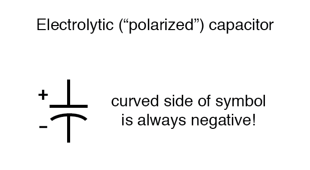
Capacitor Polarity
Polarity: Certain capacitors, notably electrolytic types, are fabricated with a thin insulating layer deposited on one electrode during manufacture. This construction makes them sensitive to voltage polarity; reversing the polarity destroys the dielectric and shorts the device. Electrolytic capacitors are clearly marked with polarity arrows or a plus sign. Non‑polarized types—ceramic, film, mylar, air—lack such markings and can be connected in either direction.
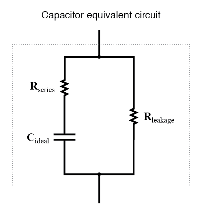
Capacitor Equivalent Circuit
Equivalent circuit: Real capacitors exhibit a finite series resistance (ESR) and a parallel leakage resistance (RL). These parasitic elements affect ripple handling, heat dissipation, and frequency response. Modern manufacturing techniques allow ESR values in the sub‑milliohm range and leakage resistances exceeding 1012 Ω, making capacitors virtually ideal for most applications.
Capacitor Physical Size
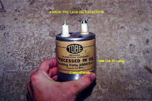
Minimizing component footprint is a key goal in modern electronics. However, size is constrained by the trade‑off between working voltage and capacitance. To increase voltage rating, the dielectric thickness must grow, which reduces capacitance unless the plate area is expanded—adding to the size. Consequently, two capacitors of identical dimensions can have vastly different capacitance and voltage ratings depending on dielectric choice.
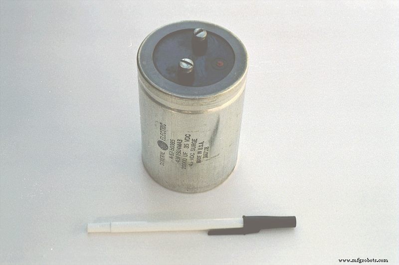
For example, a 2 µF capacitor rated for 2000 V occupies a relatively large package. If the dielectric were thinned, its capacitance could rise by up to a hundred‑fold, but the voltage rating would drop sharply. In contrast, a similarly sized electrolytic capacitor can provide 20 000 µF at only 35 V continuous (45 V intermittent) due to its ultrathin dielectric.
Below are representative samples of various capacitor types, all smaller than the examples above:
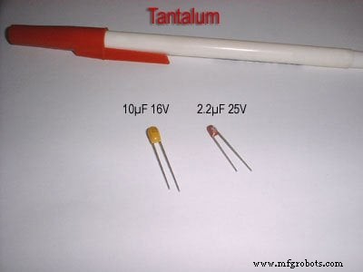
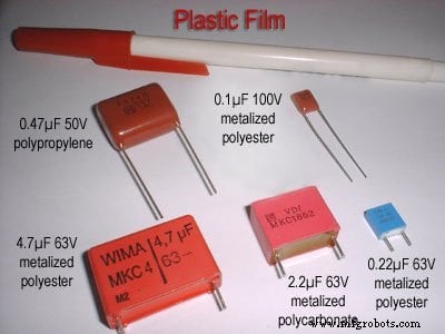
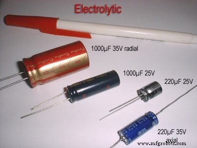
Electrolytic and tantalum capacitors are polarized and carry clear polarity markings. Electrolytic units show a negative lead arrow; some polarized capacitors indicate the positive terminal. Non‑polarized types—ceramic, film, mylar, air—lack polarity indicators.
Capacitors are ubiquitous on printed circuit boards. On the board below, every component labeled “C” is a capacitor:
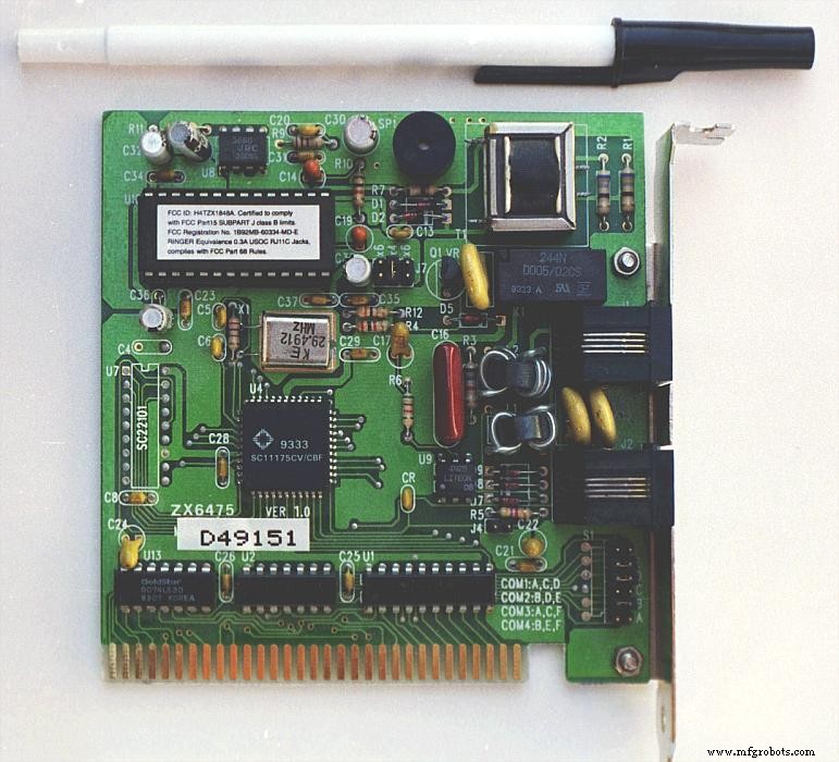
The board features standard electrolytic capacitors (C30, C36) and tantalum capacitors (C14, C19, C24, C22), which offer high capacitance in a compact form.
Even smaller surface‑mount capacitors appear on the board below, illustrating the shift toward dense, surface‑mount design:
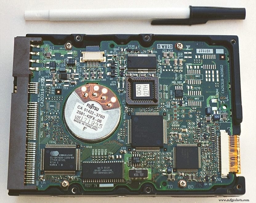
All surface‑mount devices, including these capacitors and the resistors, are selected to conserve board real estate.
RELATED WORKSHEETS:
- Capacitors Worksheet
Industrial Technology
- 555 Timer Astable Oscillator: LED Demo & Duty Cycle Exploration
- Capacitor Types: Polarized, Non-Polarized, and Variable Explained
- Key ADC Design Factors: Resolution, Sampling, and Practical Performance
- Practical Considerations for Operational Amplifiers
- Practical Battery Bank Design: Series vs Parallel, Protection, and Charging Best Practices
- Capacitors & Calculus: How Voltage Change Drives Current
- Practical Considerations for Selecting and Using Inductors
- Understanding Capacitor and Inductor Transient Response in Series RC Circuits
- Understanding Capacitor Transient Response: Charging Dynamics, Asymptotic Behavior, and SPICE Simulation
- AC Capacitor Circuits: Capacitive Reactance, Phase Shift, and Power Behavior