


Key ADC Design Factors: Resolution, Sampling, and Practical Performance
In any data‑acquisition system, the most critical ADC parameter is its resolution—the number of binary states it can produce. Because an ADC converts a continuously varying analog input into a finite set of digital codes, knowing how many distinct levels exist is essential.
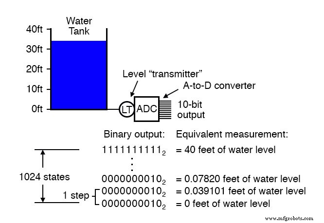
For example, a 10‑bit ADC can represent 210 = 1024 different values. Across the full 0 %–100 % range, the converter outputs the binary sequence 0000000000 to 1111111111.
Doubling the bit count to 11 provides 211 = 2048 levels, effectively halving the size of each step in the measured range.
Resolution matters most when the measurement span is large relative to the required precision. Consider monitoring the water level in a 40‑ft storage tank with a 10‑bit ADC. Zero feet corresponds to 0 % of the scale and 40 feet to 100 %. The ADC can distinguish 1024 discrete states, so each step covers 40 ft ÷ 1023 ≈ 0.0391 ft (≈ 0.469 in). This is the smallest level change the instrument can detect—just under 0.1 % of the total range.
Suppose the application demands a resolution of one‑tenth of an inch. The tank then requires 40 ft ÷ (0.1 in ÷ 12 in/ft) ≈ 4800 steps. A 10‑bit ADC supplies only 1023 steps, 11 bits give 2047, 12 bits provide 4095, and 13 bits yield 8191—more than enough. Therefore, at least a 13‑bit converter is necessary.
Another key parameter is the sample frequency (or conversion rate). This is the rate at which the ADC outputs a new code. For slowly varying signals—like tank level—the sample rate can be modest, but for audio or other high‑frequency signals, the ADC must operate much faster.
Successive‑approximation ADCs illustrate the trade‑off: with a fixed sample period, a slow signal is faithfully captured, whereas a rapid signal suffers from under‑sampling and distortion. The missed details arise because the ADC’s sample period is too long relative to the signal’s dynamics.
The theoretical limit of an ADC is the Nyquist frequency, half the sample rate. An ADC running at 5 kHz can resolve signals up to 2.5 kHz. Sampling below this threshold causes aliasing, where high‑frequency components masquerade as lower frequencies. Typical illustrations show the output waveform stretched in time and its shape altered dramatically.
In practice, a safe rule of thumb is to keep the highest measurable frequency between one‑fifth and one‑tenth of the sample rate. A common anti‑aliasing technique is to place a low‑pass filter at the ADC input, attenuating any signal above the practical limit.
Step recovery is another performance metric: it measures how quickly an ADC can adjust its output to a sudden change in the analog input. Some technologies, like tracking converters, update quickly but lag when the input steps sharply.
While no ADC is perfect, engineering choices—such as increasing clock speed or adding dedicated filtering—can improve resolution, speed, and step response.
Below is a general ranking of ADC technologies based on typical performance attributes:
- Resolution/complexity ratio: single‑slope integrating, dual‑slope integrating, counter, tracking, successive approximation, flash.
- Speed: flash, tracking, successive approximation, single‑slope integrating & counter, dual‑slope integrating.
- Step recovery: flash, successive approximation, single‑slope integrating & counter, dual‑slope integrating, tracking.
These rankings can shift depending on specific application constraints. For example, tracking ADCs respond uniformly to all step changes, whereas single‑slope or counter ADCs detect high‑to‑low steps faster than low‑to‑high ones. Successive‑approximation ADCs generally match any analog signal quickly, but tracking ADCs outperform them when the signal changes slower than one resolution step per clock cycle.
Ultimately, selecting an ADC involves balancing resolution, sampling rate, step recovery, and practical design complexity to meet the measurement requirements of your system.
Industrial Technology
- Foundations of DC Circuits: Understanding Direct Current and Core Electrical Concepts
- Determinism and Fault Tolerance: Essential Design Principles for Industrial Control Networks
- Practical Considerations for Operational Amplifiers
- Crystal and Transistor Radio Circuits: From Basic Detectors to Integrated AM/FM Receivers
- Control Circuits: Fundamentals, Applications, and Best Practices
- Practical Battery Bank Design: Series vs Parallel, Protection, and Charging Best Practices
- Practical Considerations for Selecting and Using Capacitors
- Practical Considerations for Selecting and Using Inductors
- Practical Considerations in Transformer Design: Power, Losses, and Performance
- 10 Essential Tips for Designing Low‑Noise Amplifiers