


Fundamentals of Digital Communication: From Theory to Practical Implementation
When engineering large and complex digital systems, reliable data exchange between devices is essential. Digital signals inherently resist transmission errors far better than their analog counterparts, ensuring greater integrity and clarity.
These benefits manifest in the crystal‑clear quality of digitally encoded telephone lines, the fidelity of compact audio discs, and the widespread enthusiasm within engineering for digital communications. Yet, digital transmission is not without challenges, and myriad incompatible protocols and methods still exist.
In this chapter, we delve into the fundamentals of digital communication, outlining its strengths, limitations, and key practical considerations.
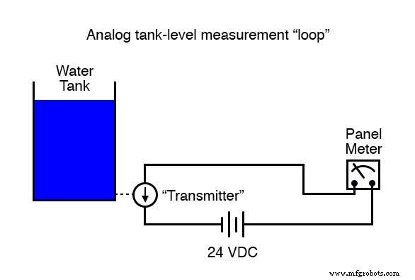
Consider a scenario where we must remotely monitor the water level in a storage tank. Our goal is to design a system that accurately measures the tank’s level and reliably transmits that data to a remote monitoring station.
Measuring the tank’s level is straightforward; a variety of instruments can be employed, including float switches, pressure transmitters, ultrasonic detectors, capacitance probes, strain gauges, and radar level sensors.
Example of Analog Communication
For illustration, we’ll use an analog level‑measuring device that outputs a 4–20 mA current loop. In this encoding, 4 mA corresponds to 0 % tank level, 20 mA to 100 %, and intermediate currents linearly represent levels between those extremes.
Transmitting this 4–20 mA signal over a pair of copper conductors would drive a calibrated panel meter at the remote site, displaying the water depth in the desired units.
While simple and robust, the analog approach is not the only viable solution. To explore digital techniques, let’s evaluate alternative monitoring strategies.
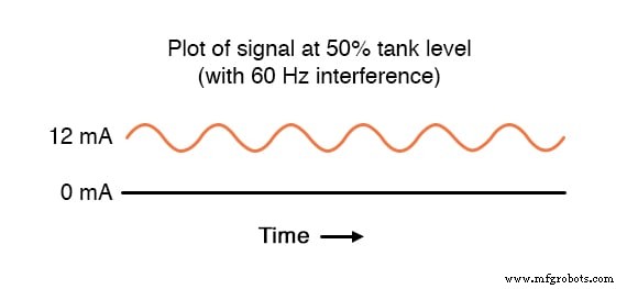
Analog systems suffer from interference: any electrical noise injected into the DC current path can be misinterpreted as a change in water level. For instance, proximity to 60 Hz AC power lines can induce inductive or capacitive coupling, introducing false “noise” into the otherwise clean loop.
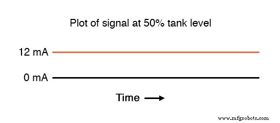
With an ideal, noiseless 4–20 mA loop, a steady 50 % tank level would appear as a flat line at 12 mA. However, real‑world conditions can distort this signal, as shown in the following illustration.
Even small voltage spikes can be amplified by the low‑impedance loop, potentially leading to significant measurement errors.
Digital signaling mitigates these issues. By replacing the analog transmitter with a set of discrete level switches positioned at different heights, each switch forms a binary “on/off” signal that is far less susceptible to noise.
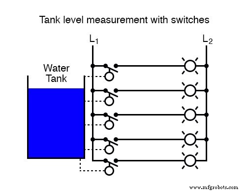
At the monitoring station, lamps or indicator LEDs reflect the state of each switch, providing a clear, digital representation of the tank level. The binary nature of the signal means that only extreme interference could flip a bit, enhancing reliability.
To increase resolution, one could install 16 switches instead of five. While this improves granularity, it also multiplies wiring requirements. A priority encoder can compress the 16‑bit pattern into a 4‑bit binary number, reducing the number of conductors to just four (plus power and ground).
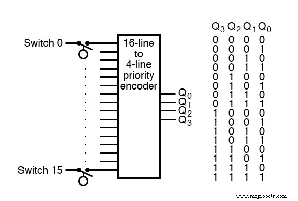
At the receiving end, a decoder translates the 4‑bit data back into 16 output signals or drives a numerical display, offering a scalable solution.
For applications demanding finer resolution, converting the original analog 4–20 mA signal to a high‑resolution digital format at the source is preferable. The analog‑to‑digital conversion can occur on the tank side, where the signal is clean, before the data is sent across the field.
Digital data transmission can occur in two modes:
- Parallel – each bit travels on its own wire, arriving simultaneously.
- Serial – bits are sent sequentially over a single channel, requiring a clock or framing protocol.
Serial transmission often reduces wiring complexity. A multiplexer or shift register can serialise the parallel data, and a corresponding demultiplexer or shift register at the destination restores the original bit pattern. Universal Asynchronous Receiver‑Transmitters (UARTs) are widely used to manage the intricacies of serial communication, simplifying the designer’s work.
RELATED WORKSHEETS
- Digital Communication Worksheet
Industrial Technology
- Digital Integrated Circuits: Foundations and Best Practices
- Digital‑Analog Conversion: Fundamentals, ADCs, and DACs
- Determinism and Fault Tolerance: Essential Design Principles for Industrial Control Networks
- Foundations and Advancements of AC Motor Technology
- Ultra‑Wideband (UWB) Technology: A Modern Wireless Standard for High‑Speed, Secure Short‑Range Connectivity
- Smart IoT Propane Tank Level Monitoring – Reliable Wireless Solution
- Real-Time IoT Oil Tank Level Monitoring for Precise Inventory Control
- Touch-Enabled Prototype Lets You Send Data Directly From Your Body
- Understanding Power, Communication, and Magnet Wire Cables: A Comprehensive Guide
- Osai GTL: Advanced High-Level Geometric Programming for CNC