


Delta‑Sigma ADC: Harnessing Oversampling for Precise Analog‑to‑Digital Conversion
Delta‑sigma (ΔΣ) analog‑to‑digital converters (ADCs) represent a sophisticated family of devices that transform continuous voltage signals into high‑resolution digital data. In mathematics and physics, the Greek capital letter Δ stands for difference or change, while Σ denotes summation. The ΔΣ architecture exploits this relationship by continuously measuring the difference between the integrator output and zero volts, then summing the resulting binary samples to recover the original analog value.
At the core of a ΔΣ converter is an integrator that receives the analog input voltage. As the input changes, the integrator’s output ramps linearly, producing a voltage whose slope is proportional to the input magnitude. A high‑speed comparator then measures whether this ramp is above or below ground, generating a single‑bit (1‑bit ADC) decision of “high” or “low.”
The comparator’s output is captured by a D‑type flip‑flop on every clock pulse. This stored bit is fed back into the integrator through a second comparator that translates the 0‑V/5‑V logic level into a bipolar ±V signal. If the integrator’s voltage is positive, the feedback pushes it toward zero; if it is negative, the feedback pushes it in the opposite direction. The loop continually hunts for the point where the integrator’s output equals zero volts, thereby keeping the integrator in a balanced state.
Schematic Diagram
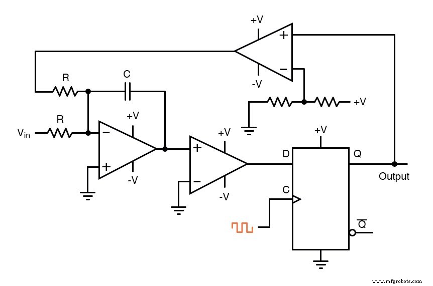
The diagram shows the summing integrator on the left, followed by the comparator (1‑bit ADC), the D‑flip‑flop that latches the bit, and finally the feedback comparator that converts the logic level back into a ±V drive for the integrator.
Output Waveforms
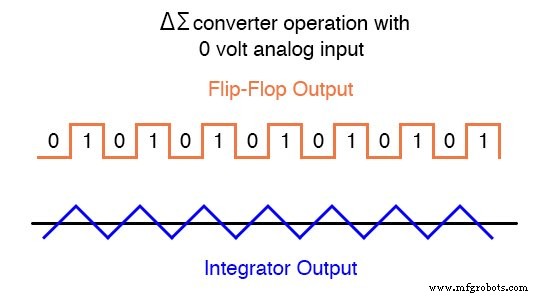
When the input voltage is zero, the integrator has no net drive to ramp in either direction. The feedback loop therefore forces the flip‑flop to oscillate between high and low states, effectively hunting for zero volts. This oscillation can be visualized in the following waveform:
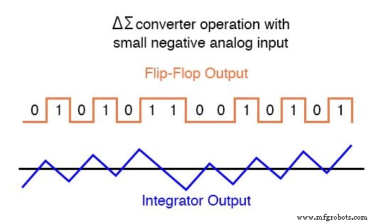
Introducing a negative analog input tilts the integrator’s ramp toward the positive side. The feedback loop compensates by increasing the proportion of high bits in the output stream, as shown here:
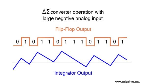
With a larger negative input, the integrator ramps even more steeply, resulting in a higher density of high bits:
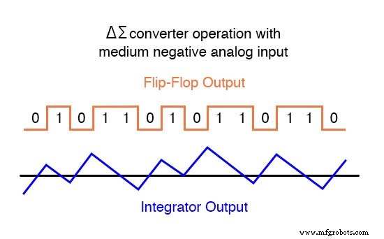
Across a full sampling interval, the ratio of high bits rises with the magnitude of the input voltage:
To obtain a conventional parallel binary output, the serial bit stream is averaged—often by a counter that tallies the number of high bits over a fixed number of clock pulses. The resulting count directly reflects the magnitude of the analog input.
Delta‑sigma converters frequently employ multiple integrator stages or multi‑bit comparators, but the core principle remains the same: oversampling. By sampling the input at a rate far above the Nyquist frequency and averaging the many 1‑bit decisions, the system achieves an effective resolution that rivals or exceeds that of a single‑shot 8‑bit ADC—though at a lower throughput.
In summary, the ΔΣ ADC architecture combines a simple integrator‑comparator loop with clever oversampling to deliver high‑resolution digital representations of analog signals, all while maintaining a compact and robust design suitable for modern embedded systems.
RELATED WORKSHEET:
- Analog-to-Digital Conversion Worksheet
Industrial Technology
- Common‑Emitter Amplifier: Design, Measurement, and Feedback Techniques
- Build a High‑Gain Differential Amplifier That Works as an Op‑Amp
- Precision Voltage Follower: Mastering Op‑Amp Feedback for Accurate Signal Tracking
- Precision Op‑Amp Integrator Lab: Bias‑Current Compensation & Analog Computation
- Special-Output Logic Gates: Complementary, Tristate, and Bilateral Switches
- Flash ADC (Parallel Analog‑to‑Digital Converter) – Design, Operation, and Applications
- Digital Ramp (Counter) ADC: Operation, Benefits, and Limitations
- Tracking ADC: Up/Down Counter for Fast, Continuous Signal Conversion
- Integrating (Single‑Slope) ADCs: Principles, Advantages, and Dual‑Slope Alternatives
- Leveraging Delta‑Sigma ADCs for Ultra‑High‑Precision Oil, Gas, and Petroleum Multisensor Systems