


Precision Voltage Follower: Mastering Op‑Amp Feedback for Accurate Signal Tracking
Parts and Materials
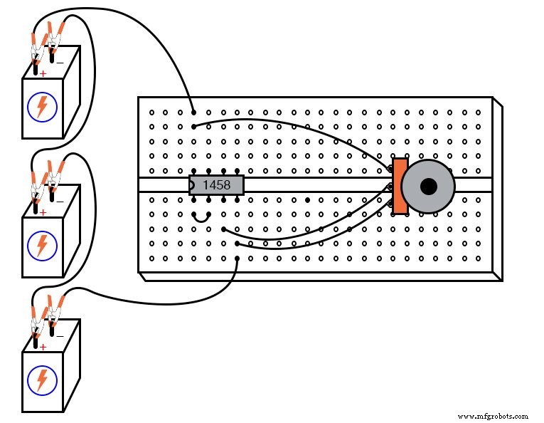
- Operational amplifier: model 1458 or 353 (Radio Shack catalog # 276‑038 and # 900‑6298, respectively)
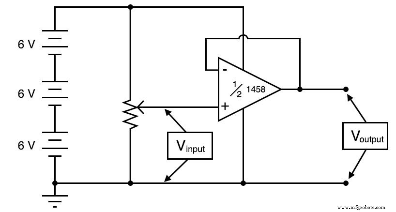
- Three 6‑volt batteries
- 10 kΩ linear‑taper potentiometer (Radio Shack catalog # 271‑1715)
Cross‑References
Lessons In Electric Circuits, Volume 3, Chapter 8: “Operational Amplifiers.”
Learning Objectives
- Demonstrate how to configure an op‑amp as a voltage follower.
- Explain the role of negative feedback in achieving a unity‑gain configuration.
- Outline a systematic troubleshooting approach for op‑amp circuits.
Schematic Diagram
Illustration
Instructions
In earlier experiments we used the op‑amp in an open‑loop configuration, which delivers its maximum voltage gain. While this is useful for comparator applications, it quickly saturates the output for any non‑zero differential input. To use the op‑amp as a true amplifier with a predictable gain, we introduce negative feedback.
By tying the output directly to the inverting (-) input, the op‑amp automatically adjusts its output so that the inverting input voltage matches the non‑inverting (+) input voltage. With this direct feedback, the circuit behaves as a voltage follower—a unity‑gain buffer that reproduces the input voltage at its output with microvolt precision.
Measure the voltage at the non‑inverting input (between the + input and ground) and at the output (between the output terminal and ground). As you rotate the potentiometer, observe the output closely tracking the input.
For a more direct assessment, place a voltmeter across the two input terminals. Throughout most of the potentiometer’s range, the error voltage will be negligible.
When the potentiometer is set to an extreme, you may notice a measurable error, especially with the 1458 or 353 models. These op‑amps cannot swing their outputs all the way to the supply rails (+18 V and 0 V). Typically they fall short by about 1–2 V, a common limitation that designers must account for. If rail‑to‑rail performance is required, consider an op‑amp like the 3130.
Voltage followers are invaluable when the source signal has high impedance and cannot tolerate loading. Although the voltage gain is unity, the follower’s low output impedance allows the signal to drive heavier loads without distortion.
They also serve as a practical diagnostic tool. If an op‑amp in a complex circuit is suspected of failing, rewire it as a simple voltage follower. A healthy op‑amp will replicate the input voltage accurately; failure to do so indicates a defective device.
Computer Simulation
Schematic with SPICE node numbers:
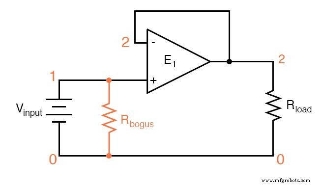
Netlist (copy the following into a text file named voltage_follower.cir):
Voltage follower vinput 1 0
rbogus 1 0 1meg


e1 2 0 1 2 999meg
rload 2 0 10k

.dc vinput 5 5 1
.print dc v(1,0) v(2,0) v(1,2)
.end
In this model, the op‑amp is represented by a dependent voltage source (e1) with an open‑loop gain of 999 MΩ. The large rbogus resistor (1 MΩ) and the load resistor (rload) provide the necessary DC paths for SPICE to converge.
Related Worksheet
- Positive Feedback Op‑Amp Circuits Worksheet
Industrial Technology
- Build a Precise, Low‑Cost Compound Potentiometer Circuit
- Voltage Follower Amplifier: Design, Build, and Measurement Guide
- Common‑Emitter Amplifier: Design, Measurement, and Feedback Techniques
- Build a High‑Gain Differential Amplifier That Works as an Op‑Amp
- Precision Voltage Follower: Mastering Op‑Amp Feedback for Accurate Signal Tracking
- Integrating (Single‑Slope) ADCs: Principles, Advantages, and Dual‑Slope Alternatives
- Understanding Negative Feedback in Op‑Amps: Voltage Followers and Stability
- Positive Feedback in Op‑Amp Circuits: Hysteresis, Comparators, and Oscillators
- Tachogenerators: Precision Speed Measurement for Industrial Motors and Equipment
- Timers & Multi-Vibrators: Types, Functions, and Digital Applications