


Build a Precise, Low‑Cost Compound Potentiometer Circuit
Parts and Materials
- Two single‑turn, linear‑taper potentiometers, 5 kΩ each (Radio Shack catalog #271‑1714)
- One single‑turn, linear‑taper potentiometer, 50 kΩ (Radio Shack catalog #271‑1716)
- Plastic or metal mounting box
- Three “banana” jack‑style binding posts, or equivalent terminal hardware (Radio Shack catalog #274‑662)
This project demonstrates how to build a precision potentiometer network on a tight budget.
While multi‑turn potentiometers are the industry standard for fine voltage division, a cost‑effective alternative is to combine multiple single‑turn potentiometers into a compound divider. The resulting network offers a compressed voltage range, enabling finer adjustment than a single unit.
For durability and aesthetics, we recommend housing the circuit in a project enclosure. Radio Shack’s pre‑assembled boxes are convenient, but a generic plastic light‑switch box can provide a more affordable and tidy solution.
“Banana” jacks are ideal for temporary connections. Their spring‑steel design ensures secure contact and is compatible with most multimeter test leads.
Cross‑References
Lessons in Electric Circuits, Volume 1, Chapter 6: “Divider Circuits and Kirchhoff’s Laws.”
Learning Objectives
- Demonstrate sound soldering technique.
- Illustrate the function and operation of potentiometers.
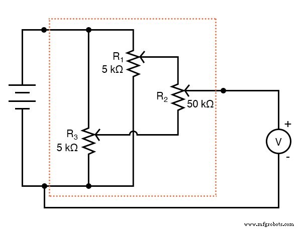
Schematic Diagram
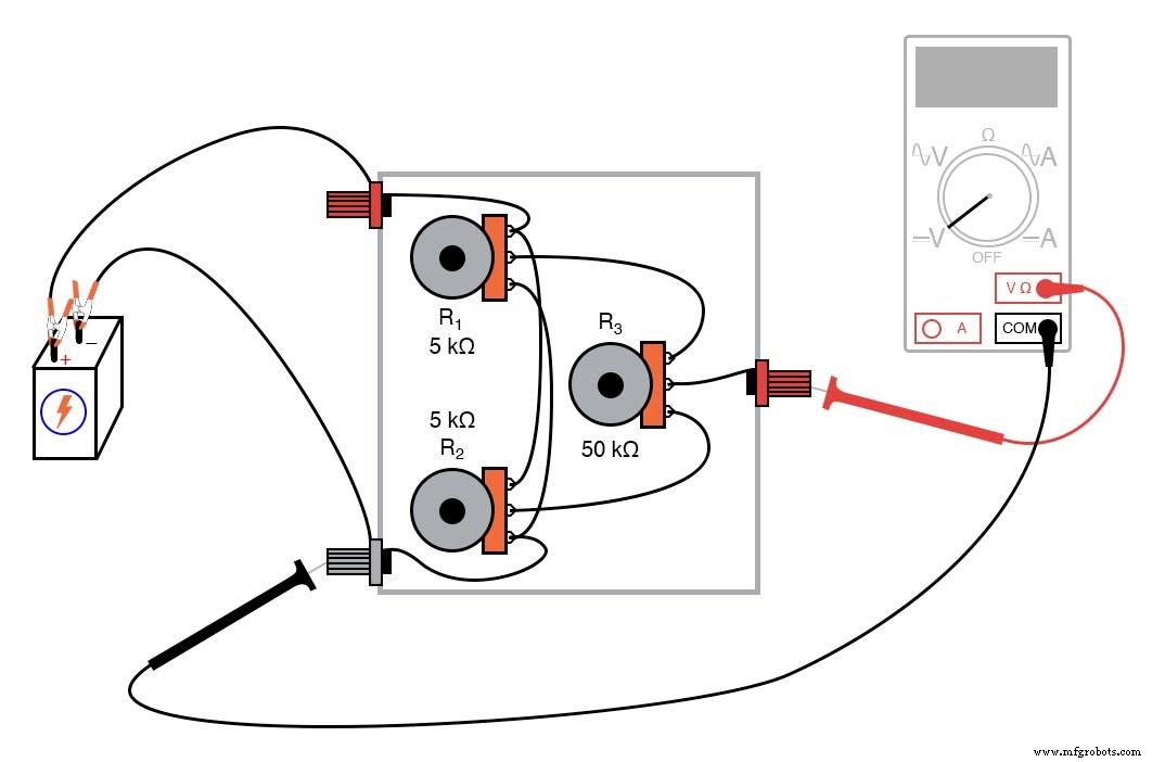
Illustration
Instructions
All connections must be soldered to ensure low resistance and mechanical stability. Twisting or taping wires can introduce unwanted resistance and compromise accuracy.
Connect a 6‑V battery to the two outer binding posts. Measure the voltage between the “wiper” post and the battery’s negative terminal with a voltmeter; this is the circuit’s output.
Because the network employs a compressed range, the output voltage achievable by adjusting potentiometer R₃ is bounded by the settings of R₁ and R₂. For example, if R₁ is set to deliver 5 V and R₂ to 3 V from the 6‑V supply, R₃’s rotation will produce an output that can only vary between 3 V and 5 V.
Follow these steps to calibrate the network:
- Turn R₃ fully clockwise so its wiper is electrically adjacent to R₁’s wiper.
- Adjust R₁ until the voltmeter reads the desired upper limit.
- Turn R₃ fully counter‑clockwise, aligning its wiper with R₂’s wiper.
- Adjust R₂ until the voltmeter reads the desired lower limit.
- Because changing R₁ or R₂ can affect the other, repeat steps 1–4 as needed to lock both limits.
R₁ and R₂ are chosen with ten‑fold lower resistance than R₃ to minimize interaction. Even with equal values, the system remains usable; it simply requires more fine‑tuning.
Once the bounds are set, rotate R₃ to obtain any intermediate voltage within that range, achieving precision that would be difficult with a single potentiometer.
Related Worksheets
- Potentiometers Worksheet
Industrial Technology
- Building a Precise Voltage Divider with a Potentiometer
- Using a Potentiometer as a Rheostat for Simple Motor Speed Control
- Differentiator Circuit – Visualizing the Rate of Change
- Precision Voltage Follower: Mastering Op‑Amp Feedback for Accurate Signal Tracking
- Precision Op‑Amp Integrator Lab: Bias‑Current Compensation & Analog Computation
- The Ultimate Precision Casting Guide: Techniques & Applications
- Understanding Precision Machining: Definition, Benefits, and Applications
- Precision Machining Explained: Key Terminology & Techniques
- Precision Grinding: Definition, Applications, and Benefits
- Precision Machining Explained: How Exact Manufacturing Shapes Modern Industries