


Customizing Resistance Ranges with Rheostats and Series‑Parallel Resistor Networks
PARTS AND MATERIALS
- Multiple 10 kΩ fixed resistors
- One 10 kΩ linear‑taper potentiometer (Radio Shack catalog # 271‑1715)
CROSS‑REFERENCES
Lessons in Electric Circuits, Volume 1 – Chapters 5, 7, 8
LEARNING OBJECTIVES
- Determine series‑parallel resistance combinations.
- Apply calibration theory and practice to adjust a rheostat.
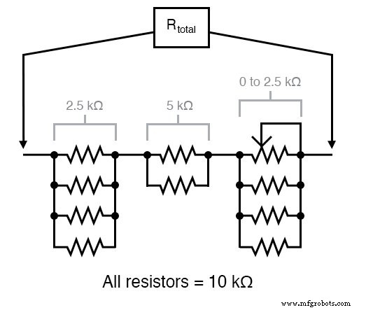
SCHEMATIC DIAGRAM
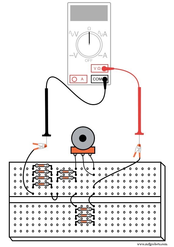
ILLUSTRATION
INSTRUCTIONS
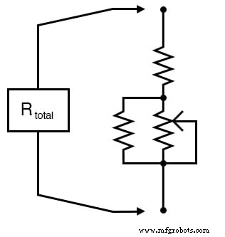
This laboratory exercise demonstrates how to tailor the resistance range of a rheostat by combining a 10 kΩ potentiometer with additional fixed resistors in series and parallel. The resulting network can be calibrated to provide any desired span and zero‑point offset, which is essential for precision meter circuits.
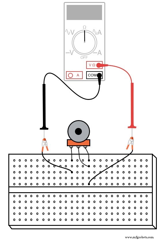
Begin by wiring the 10 kΩ potentiometer as a rheostat with no other components attached. As you turn the wiper across its full travel, the measured resistance should sweep smoothly from 0 Ω to 10 kΩ, as shown in the accompanying diagram.
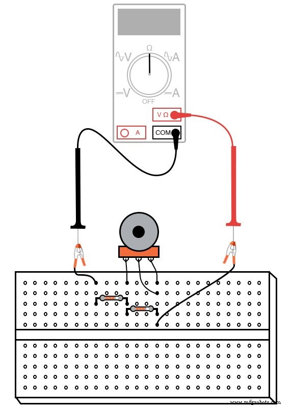
If you wish to raise the lower bound of the adjustable range—e.g., to obtain a 10 kΩ to 20 kΩ span while still sweeping the full pot—add a 10 kΩ resistor in series. Measure the total resistance while rotating the potentiometer; the zero point will have shifted upward by 10 kΩ, but the span remains 10 kΩ.
Shifting the zero point is known as zero‑calibration in metrology. The span—the difference between the high and low limits—stays unchanged unless you alter the potentiometer itself or modify the circuit topology.
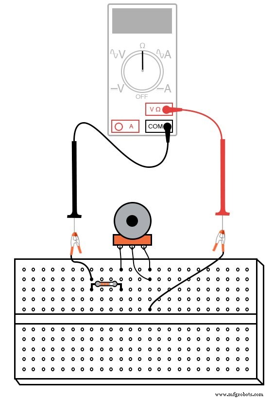
To reduce the span, place a 10 kΩ resistor in parallel with the potentiometer. This effectively halves the maximum attainable resistance, converting a 0 kΩ–10 kΩ sweep into a 5 kΩ–10 kΩ range. Consequently, the calibrated span becomes 10 kΩ to 15 kΩ.
Increasing the span requires a higher‑value potentiometer; adding series or parallel resistors can only keep the span the same or reduce it. Nevertheless, the zero point can be shifted arbitrarily high by adding series resistance.
By creatively combining multiple 10 kΩ resistors in series‑parallel networks, you can generate a wide variety of resistance ranges. For example, the following configuration yields a 7.5 kΩ to 10 kΩ span:
Such custom networks are invaluable when designing instruments like multimeters, where the internal resistance determines the measurement range. Precision in the network ensures accurate readings, while the potentiometer offers a fine‑tuning adjustment to counteract drift over time.
Experiment with different resistor arrangements to observe how the total resistance range changes, reinforcing the principles of series‑parallel calculations and calibration.
RELATED WORKSHEETS
Industrial Technology
- Using a Potentiometer as a Rheostat for Simple Motor Speed Control
- Resistor Types Explained: From Potentiometers to Thermistors
- Mastering Python For Loops: Syntax, Examples, and Advanced Patterns
- Mastering Wireless Communication Range: How Power, Data Rate, and Interference Shape Connectivity
- Ground‑to‑Ground Radio Propagation: Understanding the Impact on Wireless Links
- Hexpol TPE Launches Advanced High‑Performance Cable Compounds for Safety & Durability
- Portable Range Detector – Arduino Nano DIY Kit with HC‑SR04, 18650 Power, and 3D‑Printed Enclosure
- Arduino Ultrasonic Distance Sensor Project: HC‑SR04 Range Finder
- Polyurethane Temperature Resistance: What Temperatures Can It Withstand?
- How Current Limiting Circuits Protect Electronics & Power Supplies