


Using a Potentiometer as a Rheostat for Simple Motor Speed Control
Learning Objectives
- Understand the role of a rheostat in variable resistance applications.
- Wire a potentiometer to function as a two‑terminal rheostat.
- Demonstrate basic motor speed control using a series rheostat.
- Use a voltmeter, not an ammeter, to verify circuit continuity safely.
- Identify the purpose of connecting the unused terminal to the wiper for protection against wiper failure.
Parts and Materials
- 6‑volt battery
- Single‑turn, 5 kΩ linear‑taper potentiometer (e.g., Radio Shack #271‑1714)
- Small permanent‑magnet hobby motor (e.g., Radio Shack #273‑223 or equivalent)
For this experiment, use a low‑value potentiometer—no higher than 5 kΩ—to keep the motor responsive.
Cross‑References
Lessons In Electric Circuits, Volume 1, chapter 2: “Ohm’s Law”
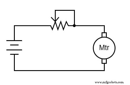
Schematic Diagram
Wiring Illustration for Using a Potentiometer as a Rheostat
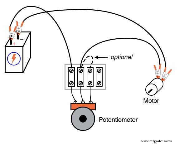
Instructions for Potentiometer Wiring
A potentiometer is most often used as a voltage divider, but it can also serve as a simple variable resistor—a rheostat—by connecting only two terminals.
To convert a potentiometer into a rheostat, connect the wiper to one outer terminal and leave the third terminal disconnected. The resulting two‑terminal device offers a continuously adjustable resistance between the selected terminals.
For example, if you connect the wiper to the left outer terminal, turning the shaft to bring the wiper closer to the right outer terminal decreases resistance. Reversing the connection simply swaps the direction of change.
Using the two outer terminals together produces a fixed resistance and eliminates the variable feature, so avoid that configuration when a rheostat is required.
Attach the potentiometer as shown in the schematic and observe how the motor’s speed varies with shaft position. Experiment with swapping the connected terminals to see how the direction of speed change reverses.
With a high‑resistance potentiometer, the motor may not turn until the wiper is very close to the connected outer terminal. This illustrates how the rheostat limits current and, consequently, motor speed.
Although this method provides a simple means of speed control, it is inherently inefficient: the rheostat dissipates a significant portion of the supplied power as heat. More advanced control—such as PWM via a transistor—achieves efficient speed regulation, but that falls outside the scope of this basic experiment.
For added reliability, many circuits tie the unused terminal to the wiper. While this does not affect resistance control, it preserves a conductive path if the wiper loses contact with the resistive track—a common failure in older potentiometers.
To test this protection, disconnect the middle terminal and verify that voltage still appears across the motor, confirming continuity.
Using Motor Voltage is a Safer Alternative to Measuring Circuit Current
When verifying that a circuit is complete, measuring voltage across the motor is preferable to inserting an ammeter. An ammeter requires a series connection, which can inadvertently short the supply if the instrument is faulty. A voltmeter, on the other hand, poses no such risk, making it the safer choice for safety‑critical measurements.
Related Worksheets
- Potentiometers Worksheet
Industrial Technology
- Build a Precise, Low‑Cost Compound Potentiometer Circuit
- Customizing Resistance Ranges with Rheostats and Series‑Parallel Resistor Networks
- Half‑Wave Rectifier Experiment: Build, Measure, and Simulate a Simple AC‑to‑DC Motor Circuit
- Precision Op‑Amp Integrator Lab: Bias‑Current Compensation & Analog Computation
- Resistor Types Explained: From Potentiometers to Thermistors
- Understanding Contactors: Types, Functions, and Overload Protection
- Variable Reluctance Motors: Types, Operation, and Applications
- Stepper Motors: Types, Characteristics, and Practical Applications
- Understanding AC Commutator Motors: Design, Types, and Applications
- Rheostats vs. Potentiometers: Functionality and Key Differences