


Variable Reluctance Motors: Types, Operation, and Applications
The variable reluctance motor operates on the principle that an unrestrained iron piece naturally moves to complete a magnetic flux path with minimal reluctance, the magnetic equivalent of electrical resistance.
Synchronous Reluctance
When the rotating field of a large synchronous motor with salient poles is de‑energized, it can still generate 10–15 % of its rated synchronous torque. This residual torque arises from the varying reluctance around the rotor during a revolution. Although not commercially viable for large motors, synchronous reluctance designs are practical and cost‑effective at smaller scales.
By adding matching slots to the conductorless rotor of an induction motor, a synchronous reluctance motor is obtained. It starts like an induction motor but quickly locks into a low‑level synchronous torque driven by the changing reluctance as stator and rotor slots align.
Such motors deliver moderate synchronous torque, yet suffer from low power factor, limited pull‑out torque, and reduced efficiency—limitations that persisted until the advent of semiconductor power control.
Switched Reluctance
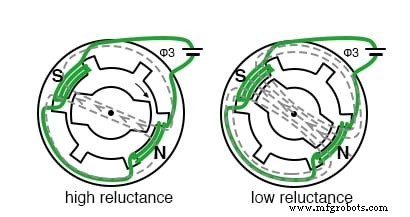
A switched reluctance motor (SRM) consists of an iron rotor with poles but no windings, paired with a multi‑phase stator. When a stator pole pair is energized, the rotor rotates toward the path of least magnetic reluctance, as illustrated below.
Sequential phase switching propels the rotor step‑by‑step, following the magnetic flux that always seeks the path of lowest reluctance. The following simplified diagram shows the rotor movement and associated waveforms.
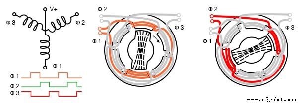
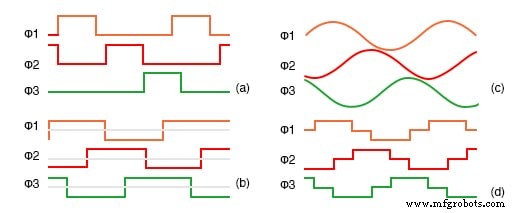
If one end of each 3‑phase winding is common, the SRM can be driven like a stepper motor: a wave drive sequence pulls each coil to ground in turn, causing the rotor to advance in 60° increments. Multiple waveforms are possible: unipolar wave drive (a), bipolar full step (b), 6‑step sine approximation (c), and true sine wave (d) generated by PWM.
Doubling the stator pole count reduces speed while boosting torque, often obviating the need for gear reduction. When the motor is intended for discrete stepping, stopping, and starting, it is referred to as a variable reluctance stepper motor.
Electronic‑Driven Variable Reluctance Motor
While SRMs perform poorly when directly powered from the mains, modern microprocessors and solid‑state drivers enable them to become economical, high‑performance solutions for high‑volume applications.
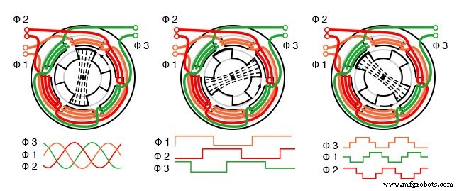
Sequentially switching the field coils generates a rotating magnetic field that drags the irregularly shaped rotor along the path of least reluctance. However, the torque‑current relationship is highly nonlinear, making precise control essential.
The electronic‑driven design mirrors a brushless DC motor but lacks a permanent‑magnet rotor, simplifying construction. Although the controller is more complex than for a BLDC, it eliminates brushes, commutators, and rotor windings, lowering manufacturing cost for large runs.
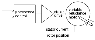
Effective control requires accurate rotor‑position sensing—typically via optical or magnetic encoders—or back‑EMF monitoring. A microprocessor then executes sophisticated switching algorithms, often within a servo loop, to regulate torque and speed and to minimize ripple torque and audible noise.
Because ripple torque is minimized, these motors excel in continuous high‑speed operation. They are already used in energy‑efficient vacuum‑cleaner fans, industrial pumps, and high‑speed fan motors, such as a 100,000 rpm fan used in a modern vacuum cleaner.
Advantages
- Simple, brush‑less construction—no commutator, rotor windings, or permanent magnets.
- High efficiency and reliability compared to conventional AC or DC motors.
- Robust starting torque.
- Cost‑effective at high production volumes.
- Excellent performance in high ambient temperatures.
- Accurate speed control achievable with high‑volume manufacturing.
Disadvantages
- Non‑linear torque‑current characteristic complicates control.
- Precise phase switching is required to suppress ripple torque.
- Phase‑current regulation is essential for smooth operation.
- Potential acoustic and electrical noise.
- Not suited to low‑volume production due to complex control needs.
Industrial Technology
- Using a Potentiometer as a Rheostat for Simple Motor Speed Control
- Half‑Wave Rectifier Experiment: Build, Measure, and Simulate a Simple AC‑to‑DC Motor Circuit
- Understanding Contactors: Types, Functions, and Overload Protection
- Stepper Motors: Types, Characteristics, and Practical Applications
- Understanding AC Commutator Motors: Design, Types, and Applications
- Raspoulette: Solar‑Powered Autonomous Coop Door System Prototype
- SmartWay: Comprehensive Kit for Vibrating Motor, RGB LED, GPS Module & Arduino MKR Fox 1200 Projects
- M1 Rover: Outdoor Autonomous Robot for Rough Terrain
- Step-by-Step Guide to Inspecting and Diagnosing DC Motor Issues
- Understanding Linear Motors: From Electrical Energy to Precise Linear Motion