


Specialized Motors: Shaded‑Pole, Servo, Hysteresis, and Eddy‑Current Clutch Applications
Shaded Pole Induction Motor
Shaded‑pole induction motors generate starting torque by incorporating a shorted copper loop in each stator pole, positioned 30° to 60° from the main winding. Typically, one‑third of a pole is wrapped with a bare copper strap.
The shading coils create a lagging, damped magnetic flux that is 30° to 60° behind the main field. When combined with the undamped main component, the result is a rotating field that imparts a modest starting torque.
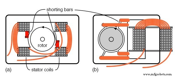
Shaded pole induction motor, (a) dual coil design, (b) smaller single‑coil version
Because the starting torque is inherently low, shaded‑pole motors are produced only in sizes below 50 W. Their simplicity and low cost make them ideal for small fans, air circulators, and other low‑torque applications. Speed can be reduced by inserting series reactance to limit current and torque, or by switching between motor coil taps.
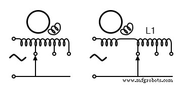
Speed control of shaded pole motor
2‑Phase Servo Motor
A two‑phase servo motor is a key component of a closed‑loop system that blends electronic, mechanical, and electrical elements. By removing the iron core from the rotor, only an aluminum cup remains to rotate, dramatically reducing inertial mass. The iron core is re‑inserted into the cup as a stationary part that completes the magnetic circuit. This lightweight construction allows the rotor to accelerate rapidly compared with a squirrel‑cage design.

High acceleration 2‑φ AC servo motor
In operation, one winding is powered directly from the single‑phase supply, while the other is driven by an amplifier. The first winding receives a 90° phase‑shifted voltage supplied through a series capacitor. The second winding is fed a variable‑amplitude sine wave that governs motor speed; a 180° phase reversal reverses direction. The variable sine wave is generated by an error amplifier. For instance, aircraft control surfaces are positioned using 400 Hz, two‑phase servo motors.
Hysteresis Motor
A hysteresis motor replaces the low‑hysteresis, silicon‑steel laminated rotor of a conventional induction motor with a slotless, winding‑free cylinder made of hardened magnet steel. This design amplifies the rotor’s magnetic lag. The resulting low‑torque synchronous motor delivers a constant torque from stall up to synchronous speed. Due to its low torque, hysteresis motors are limited to very small sizes and are typically used for constant‑speed tasks such as clock drives and, historically, phonograph turntables.
Eddy Current Clutch
When the stator of an induction or synchronous motor is mounted to rotate independently of the rotor, the assembly functions as an eddy‑current clutch. The stator coils are energized with DC and mechanically linked to the load. The squirrel‑cage rotor remains connected to the driving motor. The motor is initially started without DC excitation; as the clutch is engaged, the DC voltage is increased from zero to the required level, producing a continuously variable torque. This operation is analogous to the eddy‑current mechanism used in analog automotive speedometers.
Summary: Other specialized motors
- The shaded pole induction motor, used in under 50‑watt low‑torque applications, develops a second phase from shorted turns in the stator.
- The hysteresis motor is a small, low‑torque synchronous motor once used in clocks and phonographs.
- The eddy current clutch provides an adjustable torque.
Industrial Technology
- Stepper Motors: Types, Characteristics, and Practical Applications
- Brushless DC Motors: Design, Construction, and Advanced Applications
- Tesla Polyphase Induction Motors: Design, Operation, and Applications
- Understanding Single‑Phase Induction Motors: Types, Operation, and Efficiency Improvements
- Understanding AC Commutator Motors: Design, Types, and Applications
- Engineering Precise Motor Controls for Advanced Robotic Systems
- Extending Motor Life: Expert Maintenance Tips
- Motor Storage Maintenance: Best Practices to Preserve Performance
- Master DC & Servo Motor Control with Arduino – Step-by-Step Tutorial
- Understanding BLDC Motors: A Professional Guide