


Selsyn (Synchro) Motors: Applications, Types, and Control Systems
In most wound‑rotor induction motors, the rotor windings are shorted after the machine starts. During the start‑up phase, a series resistance limits the high inrush current. When two motors share a common starting resistance, they remain synchronized throughout the start‑up period. This feature is essential for equipment that must spin in unison, such as printing presses and drawbridges.
Once the motors are fully engaged, the rotor windings are shorted and the synchronizing torque disappears. The greater the starting resistance, the stronger the synchronizing torque that keeps the pair in sync.
When the starting resistors are removed but the rotors are still paralleled, the motors exhibit no starting torque yet retain a substantial synchronizing torque. This arrangement is known as a selsyn – short for “self‑synchronous.”
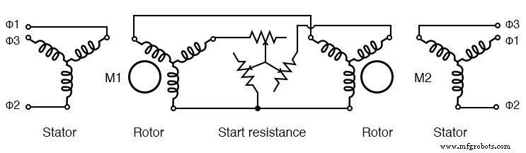
Starting wound‑rotor induction motors from common resistors
During operation, a selsyn’s rotor can remain stationary while the other’s shaft turns by an angle θ. The mechanical coupling ensures that a rotation of one shaft forces the other to follow, and any drag applied to one side is felt on the other. Although large, multi‑kilowatt selsyns exist, most applications use small units of only a few watts for remote position indication in instrumentation.
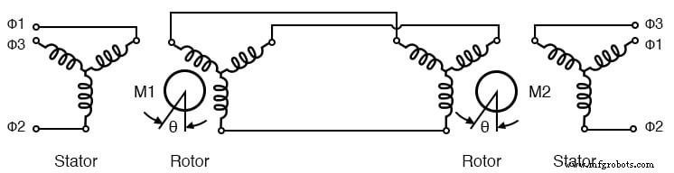
Selsyns without starting resistance
Instrumentation Synchros (TX & RX)
Instrumentation synchros, also called “synchros,” employ single‑phase AC‑powered rotors that run parallel to a three‑phase stator. The stators are not externally energized; they receive power from a common three‑phase supply that feeds both units.
When the transmitter (TX) and receiver (RX) rotors are at the same angle, the induced voltages in the stator windings are identical, and no current flows. If the shaft angles diverge, the resulting phase difference causes a stator current that develops torque, causing the receiver shaft to follow the transmitter. Either shaft can be driven, but the receiver acts as an electrically locked follower.
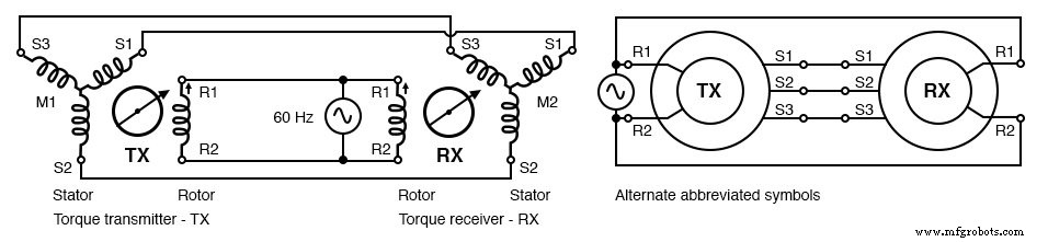
Synchros have single‑phase powered rotors
Both the TX and RX are electrically identical. The receiver typically incorporates inertial damping, while the transmitter may be substituted for a receiver if needed. Synchros are most often used for remote position sensing—for example, a transmitter attached to a radar antenna reports the antenna’s orientation to a control room indicator. They are available for 240 Vac 50 Hz, 115 Vac 60 Hz, 115 Vac 400 Hz, and 26 Vac 400 Hz power supplies.
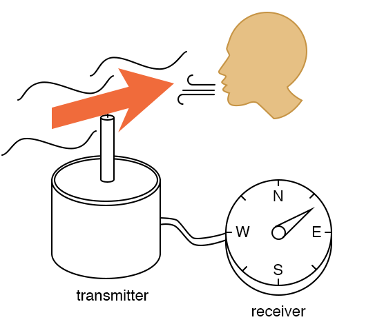
Synchro application: remote position indication
Differential Transmitter‑Receiver (TDX & TDR)
A torque differential transmitter (TDX) features a three‑phase rotor and stator. It accepts a shaft angle input and an electrical angle input, producing a combined electrical angle on the stator outputs. This output can be routed to a receiver to display the sum or difference of two angular positions.
For instance, a shipboard radar antenna’s TX encodes the antenna’s angle relative to the ship’s bow. By adding the ship’s heading from a gyrocompass via a TDX, the receiver can display the antenna’s true‑north bearing, regardless of the vessel’s orientation.
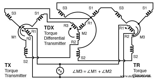
Torque differential transmitter (TDX)
Conversely, a torque differential receiver (TDR) accepts two electrical angle inputs and outputs the angular sum or difference on its shaft. The TDX is a transmitter; the TDR is a receiver.
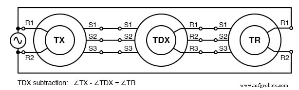
TDX subtraction
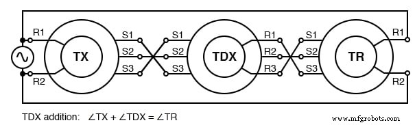
TDX addition
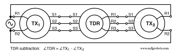
TDR subtraction
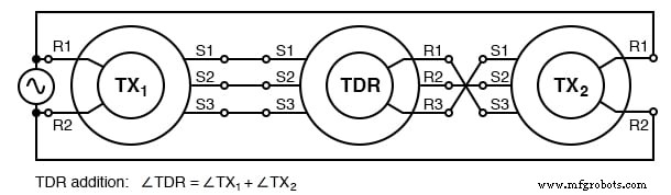
TDR addition
Control Transformer (CT)
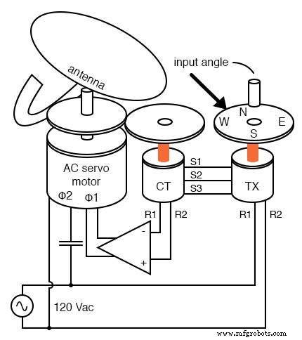
The control transformer is a specialized synchro transmitter with a rotor that has more turns than the standard TX or RX. It is highly sensitive to the null position—when the rotor is at a 90° angle to the stator’s magnetic field—making it ideal for servo‑feedback systems.
Unlike TX or RX, a CT does not transmit torque. Its rotor output is zero at the null; any deviation generates an AC error voltage proportional to the angular displacement. A servo motor driven by this error signal adjusts the shaft until the CT reaches the commanded position, closing the loop.
Control transformer (CT) detects servo null
In a typical application, the TX sets the desired antenna angle. The CT, coupled to the antenna shaft, senses the actual angle and feeds back to the servo amplifier, which drives a motor (often a 2‑phase AC servo) until the CT nulls out. For heavy loads, large DC servo motors are preferred due to their higher efficiency and easier speed control.
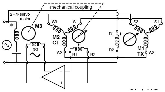
Servo uses CT to sense antenna position null
Aircraft applications frequently use 400 Hz components—TX, CT, and the servo motor—to reduce the size and weight of the magnetic assemblies. The higher frequency allows the components to be smaller while maintaining the same performance.
Resolver
A resolver converts a shaft angle into sine and cosine voltages. It has two stator windings spaced 90° apart and a single rotor winding driven by AC. When the rotor shaft rotates, the stator produces voltages proportional to sin(θ) and cos(θ).
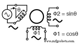
Resolver converts shaft angle to sine and cosine of the angle
Resolvers are invaluable in radar systems, where a radar’s distance output (a sine wave voltage) and bearing angle (shaft angle) are combined to produce Cartesian coordinates (X, Y). The X and Y components can then be displayed on a map. A TX can be adapted for resolver use via a Scott‑T transformer, which converts the TX’s three‑phase output into the required quadrature pair.

Scott‑T converts 3‑phi to 2‑phi enabling TX to perform the resolver function
Alternative designs, such as the inductosyn, offer higher resolution for rotary applications.
Key Takeaways
- A synchro (or selsyn) is a rotary transformer that transmits shaft torque.
- The torque transmitter (TX) turns a mechanical shaft angle into three‑phase electrical outputs.
- The torque receiver (RX) converts a three‑phase electrical angle into a mechanical shaft torque.
- The torque differential transmitter (TDX) adds an electrical angle to a shaft angle, outputting a summed electrical angle.
- The torque differential receiver (TDR) combines two electrical angles into a shaft torque.
- The control transformer (CT) detects a null position and is used in servo feedback loops.
- A resolver outputs sin(θ) and cos(θ) voltages for precise angular measurement.
- A Scott‑T transformer can convert a TX’s three‑phase output into resolver‑style quadrature signals.
Industrial Technology
- Foundations and Advancements of AC Motor Technology
- Synchronous Motors: Design, Operation, and Applications
- Stepper Motors: Types, Characteristics, and Practical Applications
- Brushless DC Motors: Design, Construction, and Advanced Applications
- Tesla Polyphase Induction Motors: Design, Operation, and Applications
- Wound‑Rotor Induction Motors: Design, Advantages, and Variable‑Speed Applications
- Understanding Single‑Phase Induction Motors: Types, Operation, and Efficiency Improvements
- Specialized Motors: Shaded‑Pole, Servo, Hysteresis, and Eddy‑Current Clutch Applications
- Selsyn (Synchro) Motors: Applications, Types, and Control Systems
- Understanding AC Commutator Motors: Design, Types, and Applications