


Wound‑Rotor Induction Motors: Design, Advantages, and Variable‑Speed Applications
A wound‑rotor induction motor features a stator identical to a squirrel‑cage motor, but its rotor contains insulated windings that exit through slip rings and brushes. While no power is ever supplied to the slip rings, they serve a crucial role during start‑up: they allow a series resistance to be inserted across the rotor windings. Once the motor reaches running speed, this resistance is shorted out, making the rotor behave electrically like a squirrel‑cage rotor.
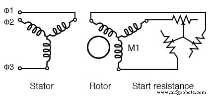
Wound rotor induction motor
Why is a resistance inserted in series with the rotor?
Large squirrel‑cage motors can draw 500–1000% of full‑load current during starting. The added resistance dramatically reduces the locked‑rotor current and, more importantly, increases the starting torque. As the rotor resistance is increased from R0 to R1 to R2, the breakdown torque peak shifts leftward, reaching its maximum at zero speed. This high torque at stand‑still is essential for starting highly inertial loads.
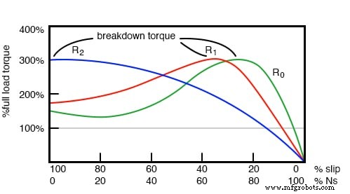
Breakdown torque peak is shifted to zero speed by increasing rotor resistance
Although the series resistance lowers the torque available at full speed, the resistance is removed once the rotor has spun up. The heat generated during start‑up is then dissipated externally in the starting resistor, keeping the motor body cooler.
One drawback of wound‑rotor motors is the added complexity and maintenance required for brushes and slip rings.
This motor configuration is ideal for starting heavy, high‑inertia loads. With a high starting resistance, the peak pull‑out torque is available immediately at zero speed—unlike a squirrel‑cage motor, whose peak torque only appears near 80% of synchronous speed.
Speed Control
By re‑introducing a variable resistance into the rotor circuit after start‑up, the motor’s speed can be controlled. Increasing the resistance lowers the rotor current, reducing speed. However, the high starting torque and shifted breakdown torque are only present at low speeds. At higher speeds, the motor behaves similarly to a squirrel‑cage motor.
Typical resistance values are denoted R0, R1, R2, and R3, with the value increasing from zero to the maximum. A higher resistance at R3 can further reduce speed. Speed regulation is best within the 50–100% full‑speed range, and it performs well with variable‑speed loads such as elevators and printing presses.
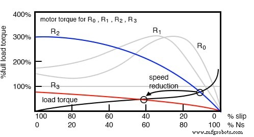
Rotor resistance controls the speed of a wound‑rotor induction motor
Doubly‑Fed Induction Generator (DFIG)
When a wound‑rotor motor is driven above synchronous speed, it can act as a generator. Because both the stator and rotor are electrically accessible, this machine is known as a doubly‑fed induction generator, unlike the singly‑fed version that only connects to the stator.
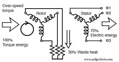
Rotor resistance enables over‑speed operation of a doubly‑fed induction generator
The DFIG can vary its speed over a range of ±30–50% relative to synchronous speed. By inserting resistance into the rotor circuit, excess energy is absorbed when the machine overspeeds, while negative resistance can supply additional energy when underspeeds. In practice, the resistance is replaced by a power‑converter that feeds or extracts energy from the rotor, improving overall efficiency.
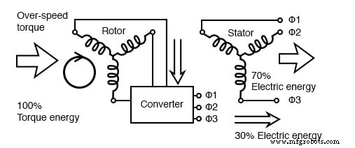
Converter recovers energy from the rotor of the doubly‑fed induction generator
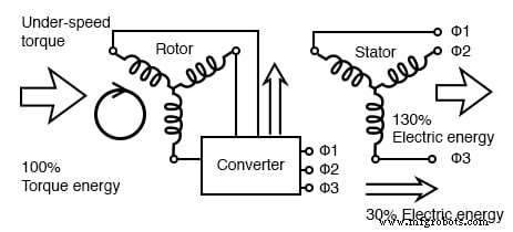
Converter borrows energy from the power line for the rotor of the doubly‑fed induction generator, allowing it to operate efficiently under and over synchronous speed
In this configuration, the rotor can effectively “borrow” or supply power to the stator, allowing the generator to maintain a 60 Hz output even when its speed deviates from synchronous speed. Theoretically, a lossless DFIG would deliver exactly 100% of the mechanical power to the grid; in practice, the rotor’s contribution can boost the apparent output to around 130% of the mechanical input, with the extra energy absorbed or supplied by the converter.
Key Qualities of Wound‑Rotor Induction Motors
- High starting torque for heavy, inertial loads.
- Lower starting current than squirrel‑cage motors.
- Speed can be regulated between 50% and 100% of full speed via rotor resistance.
- Requires brushes and slip rings, increasing maintenance compared to squirrel‑cage designs.
- When used as a generator, the machine becomes a variable‑speed doubly‑fed induction generator (DFIG).
Related Worksheet: AC Motor Theory Worksheet
Industrial Technology
- Foundations and Advancements of AC Motor Technology
- Synchronous Motors: Design, Operation, and Applications
- Stepper Motors: Types, Characteristics, and Practical Applications
- Brushless DC Motors: Design, Construction, and Advanced Applications
- Tesla Polyphase Induction Motors: Design, Operation, and Applications
- Understanding Single‑Phase Induction Motors: Types, Operation, and Efficiency Improvements
- Understanding AC Commutator Motors: Design, Types, and Applications
- Speedometer: From Mechanical Gauges to Digital Displays
- Troubleshooting Wound Rotor Motors: A Practical Guide
- Electric Motor Reliability Tip: Reduce Start‑Up Cycles to Protect Your Equipment