


555 Timer PWM DC Motor Speed Controller – Build & PCB Design Guide
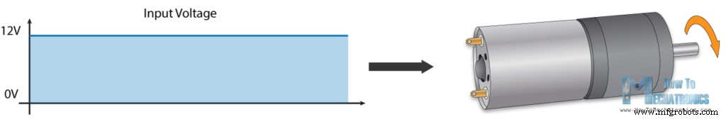
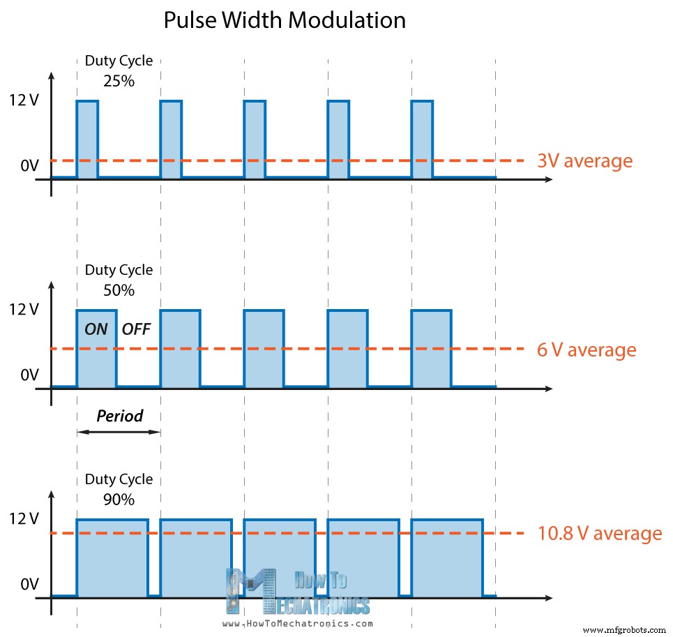
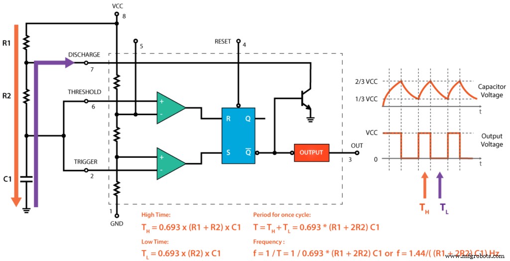
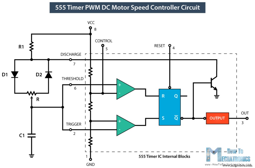
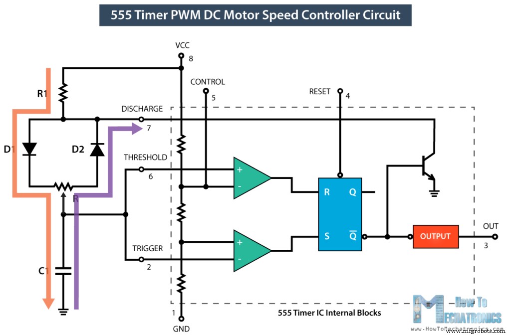
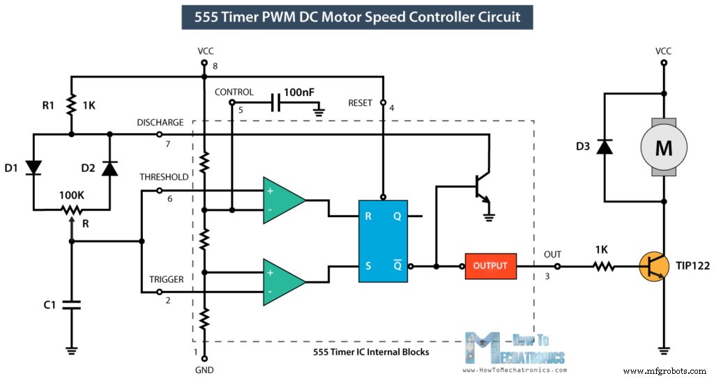
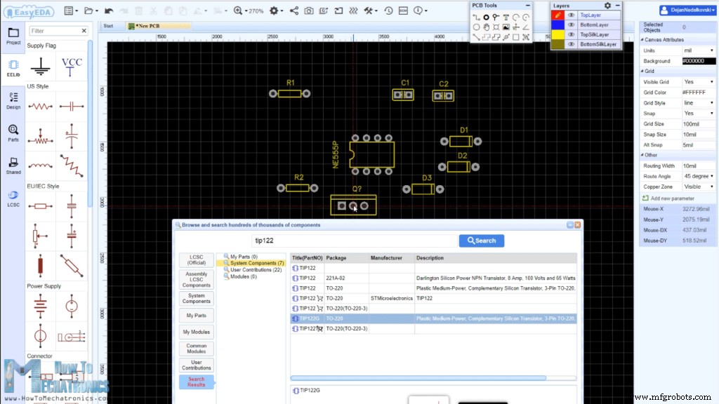
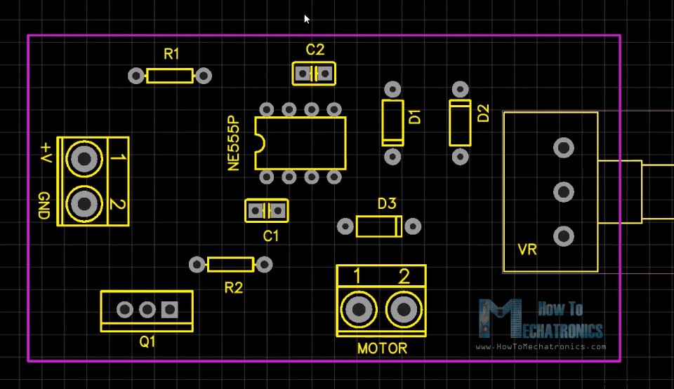
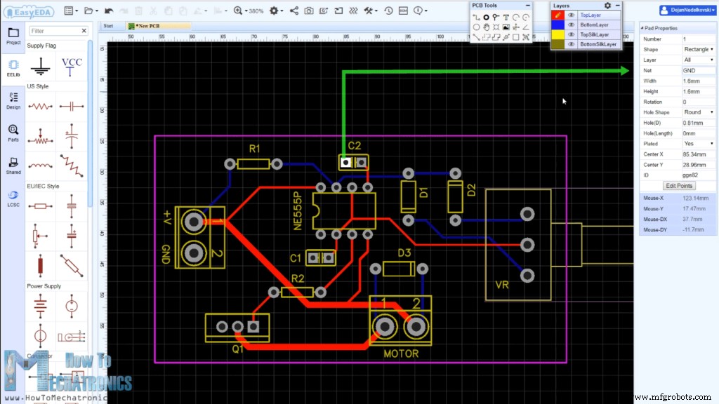
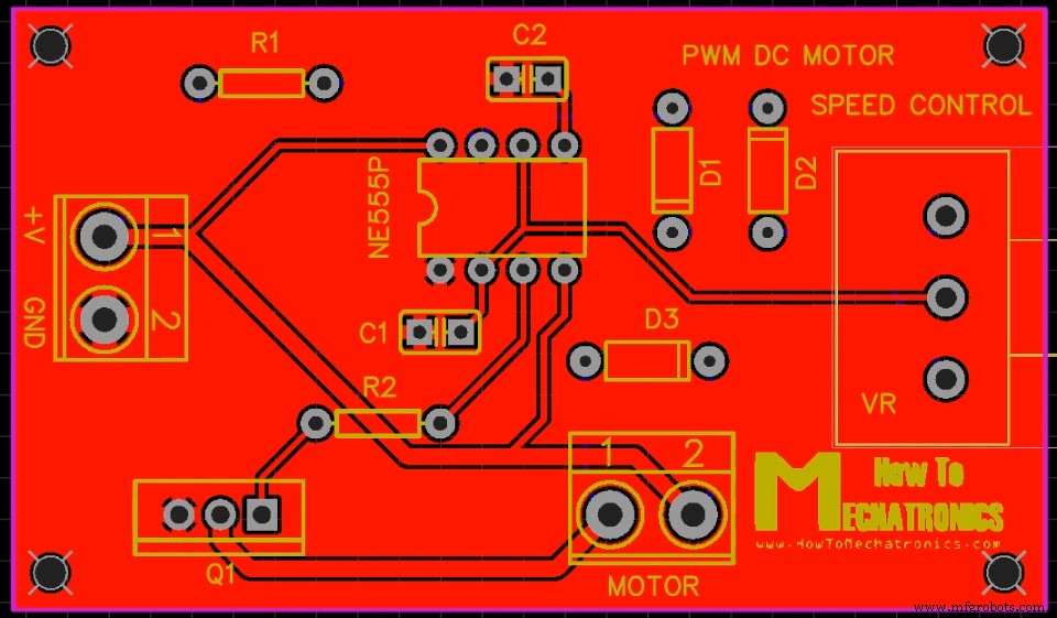
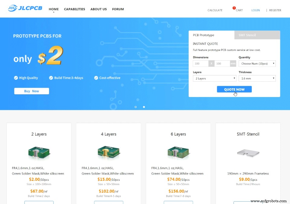
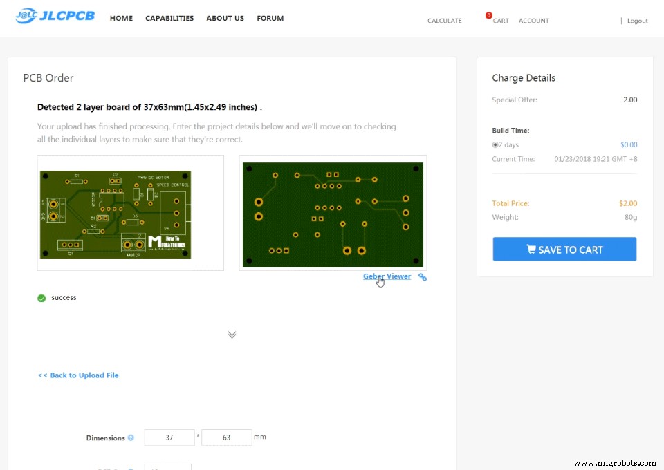
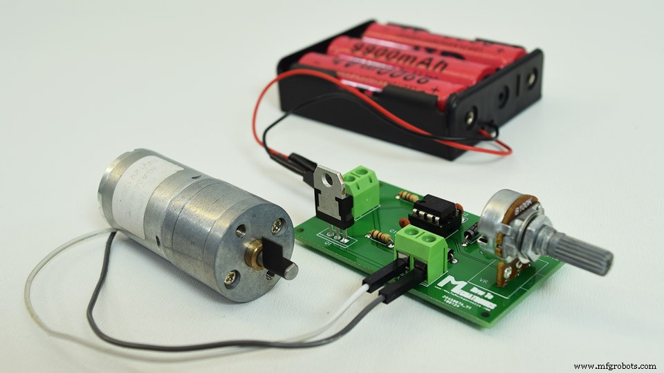
In this tutorial we will learn how to make a PWM DC Motor Speed Controller using the 555 Timer IC. We will take a detailed look how the 555 Timer PWM generator circuit works, how to use it for controlling the speed of DC motor and how to make a custom PCB for it. You can watch the following video or read the written tutorial below. We can control the speed of the DC motor by controlling the input voltage of the motor. For that purpose we can use PWM, or pulse width modulation. PWM is a method through which we can generate variable voltage by turning on and off the power that’s going to the electronic device at a fast rate. The average voltage depends on the duty cycle of the signal, or the amount of time the signal is ON versus the amount of time the signal is OFF in a single period of time. The 555 Timer is capable of generating PWM signal when set up in an astable mode. In you are not familiar with the 555 Timer you can check my previous tutorial where I explained in details what’s inside and how the 555 Timer IC works. Here’s a basic circuit of the 555 Timer operating in an astable mode and we can notice that the output is HIGH when the capacitor C1 is charging through the resistors R1 and R2. On the other hand, the output of the IC is LOW when the capacitor C1 is discharging but only through the resistor R2. So we can notice that if we change the values of any of these three components we will get different ON and OFF times, or different duty cycle of the square wave output signal. An easy and instant way to do this is to replace the R2 resistor with a potentiometer, and additionally add two diodes in the circuit. In this configuration the On time will depend on the resistor R1, the left side of the potentiometer and the capacitor C1, while the Off time will depend on the capacitor C1 and the right side of the potentiometer. We can also notice that in this configuration the period of one cycle, thus the frequency, will always be the same, because the total resistance, while charging and discharging, will remain the same. Usually the R1 resistance is much smaller than the resistance of the potentiometer, for example, 1K compared to 100K of the potentiometer. In that way we have 99% control over the charging and discharging resistance in the circuit. The control pin of the 555 Timer is not used but it’s connected to a 100nF capacitor in order to eliminate any external noise from that terminal. The reset, pin number 4, is active low so therefore it is connected to VCC in order to prevent any unwanted reset of the output. The output of the 555 timer can sink or source a current of 200mA to the load. So if the motor that we want to control exceeds this rating we need to use a transistor or a MOSFET for driving the motor. In this example, I used a (TIP122) Darlington transistor which can handle a current up to 5A. The output of the IC needs to be connected to the base of the transistor through a resistor, and in my case I used 1k resistor. For preventing any voltage spikes produced by the motor we need to use a flyback diode which is connected in parallel with the motor. Now we can move on and design a custom PCB for this circuit. For that purpose I will use the EasyEDA free online software. Here we can start by searching and placing the components on the blank canvas. The library has hundreds of thousands of components so I didn’t have any problem finding all of the required components for this PWM DC Motor Speed Controller circuit. After inserting the components we need to create the board outline and start arranging the components. The two capacitors should be placed as near as possible to the 555 Timer, while the other components can be placed wherever we want, but still in a logical arrangement according to the circuit schematic. Using the tracking tool we need to connect all the components. The tracking tool is quite intuitive and easy to work with. We can use both the top and the bottom layer for avoiding crossings and making the tracks shorter. The pads of the components that need to be connected to Ground are set to Ground through the Pad Properties tab, where we need type GND into the “Net” label when the pad is selected. We can use the Silk layer to add text to the board. Also we are able to insert an image file, so I add an image on of my website logo to be printed on the board. At the end using the copper area tool we need create the ground area of the PCB. You can find the EasyEDA project files of this project here. Once we are done with the design we just need to click the “Gerber output” button, save the project and we will be able to download the Gerber files which are used to manufacturing the PCB. We can order the PCB from JLCPCB which are the PCB fabrication service of EasyEDA, and also they are the sponsor of this video. Here we can simply drag and drop the downloaded zip file of the gerber files. After uploading we can once again review out PCB in the Gerber viewer. If everything is fine we can then select up to 10 PCBs and get them for only 2 dollars. Nevertheless, after a week the PCBs have arrived and I must admit that it’s quite satisfying to have your own PCB design manufactured. The PCBs quality is great and everything is exactly the same as in the design. Ok , so now we can move on to inserting the components onto the PCB. You can get the components needed for this example from the links below: First I inserted the smaller components, the resistors, the diodes, and the capacitors. I bent their leads on the other side so that they stay in position when I flip the board for soldering. As for the bigger components I used a masking tape to hold them in place when flipping the board. Here’s the final appearance of the board and what’s left now is to connect a DC motor and a suitable power supply for it. I used 12V high torque DC motor which I powered using there 3.7V Li-ion batteries connected in series which give around 12V. So now using the potentiometer we are able to control the speed of the DC motor, or the PWM signal produces by the 555 Timer IC. I hope you enjoyed this tutorial and learned something new. Feel free to ask any question in the comments section below.Overview
PWM DC Motor Speed Control
555 Timer PWM Generator Circuit
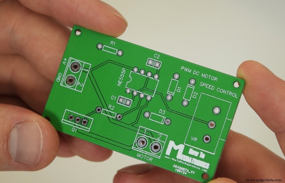
Designing a PCB for the PWM DC Motor Speed Controller
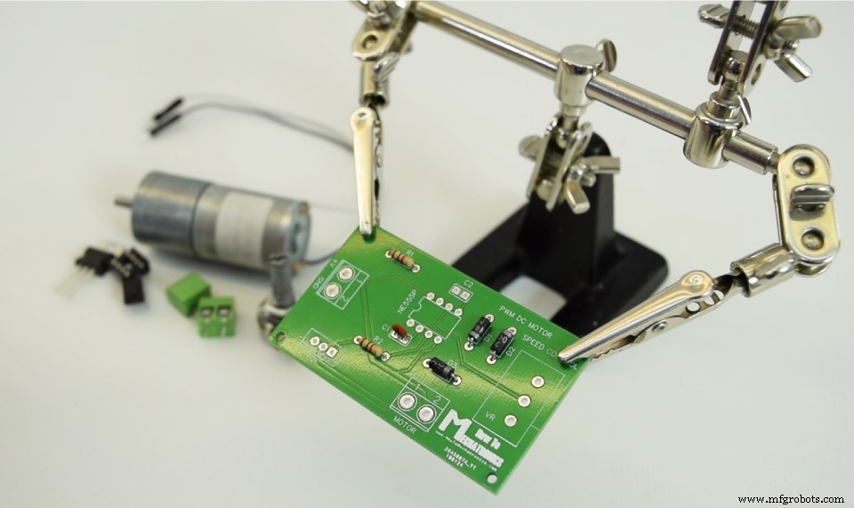
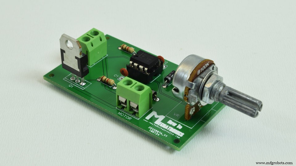
Assembling the PWM DC Motor Speed Controller PCB
Industrial Technology
- PWM Power Controller: Build a Pulse‑Width Modulated Lamp Driver
- Building a 555 Monostable Multivibrator: Step‑by‑Step Guide
- Selecting the Optimal Motor Cable for Variable Speed Drives (VSDs)
- 555 Timer Circuit Diagrams for 1‑15 Minute Intervals: Design, Build & Applications
- Advanced DC Motor Speed Control: Voltage, Rheostatic, and Flux Techniques
- Common Causes of Motor Controller Failure and How to Diagnose Them
- Choosing the Right Motor Driver & Controller for Your Robot Projects
- DIY Guide: Build Your Own DC Motor Controller
- Why a DC Motor Controller Is Essential: 7 Key Benefits
- Ultimate Guide to Motor Controllers: Function, Protection, and Usage