


Building a 555 Monostable Multivibrator: Step‑by‑Step Guide
Building a 555 Monostable Multivibrator
This beginner‑friendly tutorial walks you through the simplest 555 timer circuit, the monostable multivibrator. You’ll learn how the 555’s internal flip‑flop controls a single‑pulse output, how to calculate the timing interval, and why the design is immune to supply‑voltage variations.
Parts and Materials
- 1× 9V battery
- Battery clip (Radio Shack #270‑325)
- Mini hook clips (soldered to battery clip, Radio Shack #270‑372)
- Watch with a second hand or stopwatch
- 11/2″‑to‑2″ wire (3.8 mm to 5 mm), folded in half (red wire in illustration)
- U1 – 555 timer IC (Radio Shack #276‑1723)
- D1 – Red LED (Radio Shack #276‑041 or equivalent)
- D2 – Green LED (Radio Shack #276‑022 or equivalent)
- R1, R2 – 1 kΩ, ¼W resistors
- Rt1 – 27 kΩ, ¼W resistor
- Rt2 – 270 kΩ, ¼W resistor
- C1, C2 – 0.1 µF capacitors (Radio Shack #272‑1069 or equivalent)
- Ct – 10 µF capacitor (Radio Shack #272‑1025 or equivalent)
- Ct – 100 µF capacitor (Radio Shack #272‑1028 or equivalent)
Cross‑References
- Lessons In Electric Circuits, Vol. 1, ch. 13: “Electric fields and capacitance”
- Lessons In Electric Circuits, Vol. 1, ch. 13: “Capacitors and calculus”
- Lessons In Electric Circuits, Vol. 1, ch. 16: “Voltage and current calculations”
- Lessons In Electric Circuits, Vol. 1, ch. 16: “Solving for unknown time”
- Lessons In Electric Circuits, Vol. 4, ch. 10: “Monostable multivibrators”
Learning Objectives
- Understand the operation of a monostable multivibrator.
- Apply the RC time‑constant concept in a practical circuit.
- Configure the 555 timer as a non‑retriggerable monostable multivibrator.
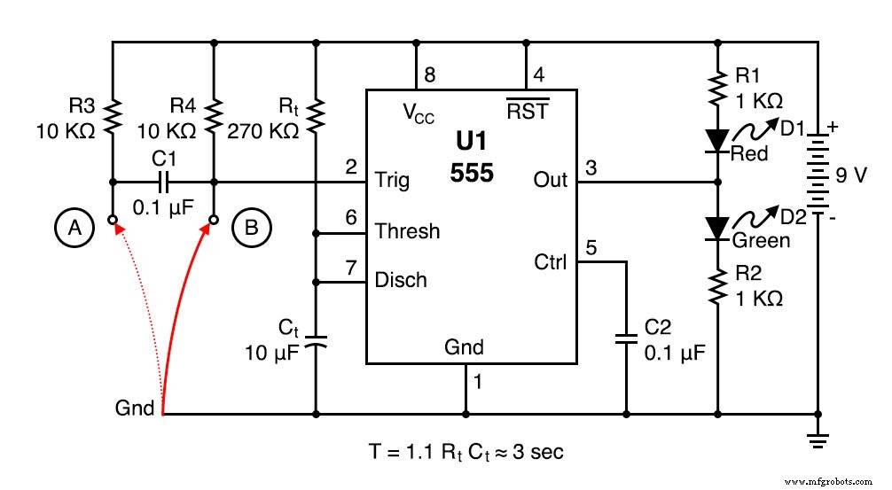
Schematic Diagram
Illustration
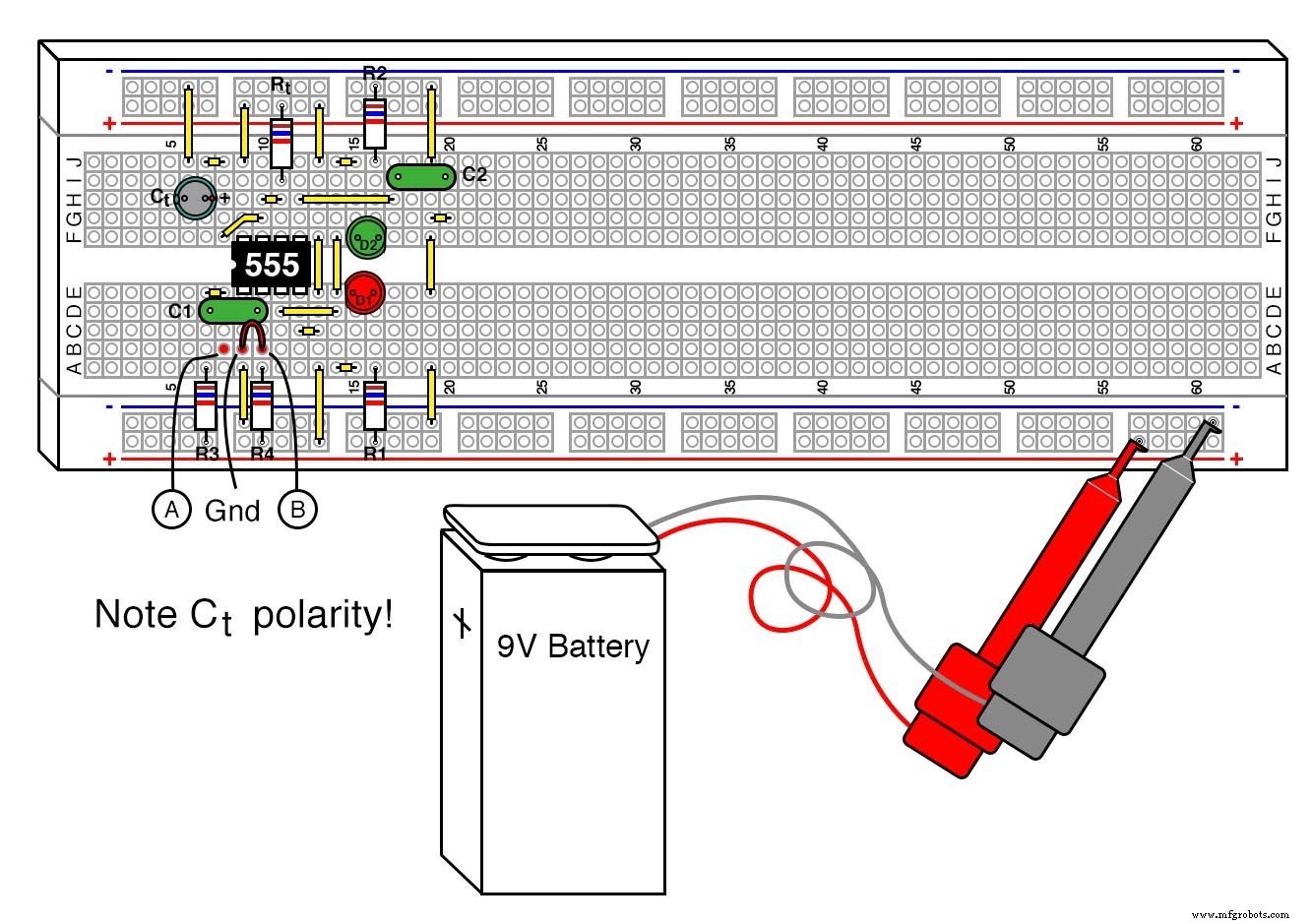
Instructions
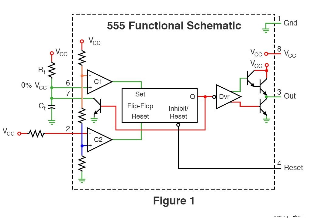
The 555 is often called the “timer” IC because of circuits like this one. In the monostable mode, a single low‑level trigger pulse causes the output to go high for a fixed duration determined by the external resistor and capacitor.
The green LED lights when the 555 output is high, and the red LED lights when it is low. This visual cue helps you verify the timing behavior.
Because the circuit is non‑retriggerable, any additional trigger pulses during the timing interval are ignored—except for a brief edge‑only condition that is addressed by the signal‑conditioning resistor and capacitor (Rt and C1).
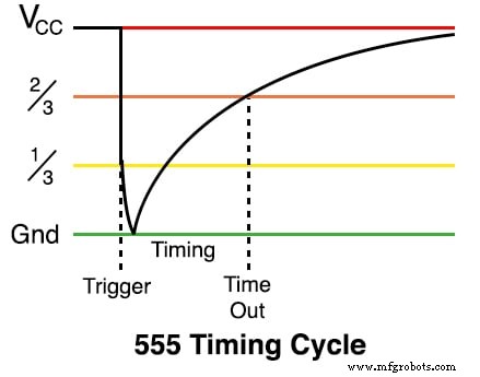
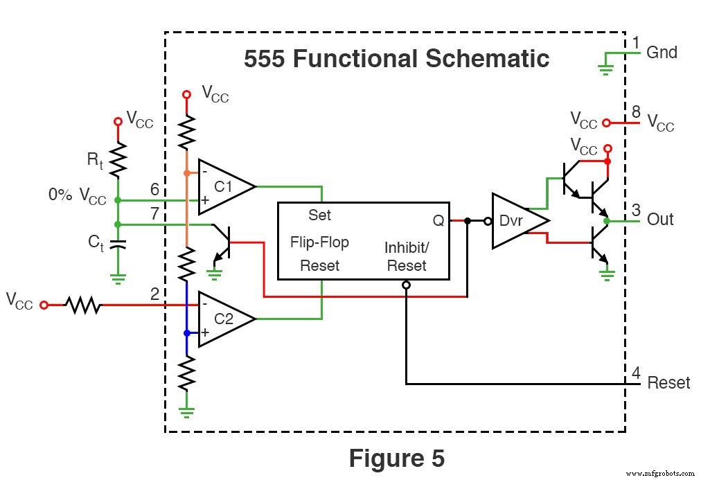
To start the timer, connect the trigger pin (pin 2) to ground. The output rises, and the timing capacitor (Ct) begins charging through Rt. Once Ct reaches 2/3 VCC, the internal flip‑flop toggles, pulling pin 7 high to discharge Ct and bring the output low.
For a 3‑second pulse, choose Rt = 27 kΩ and Ct = 10 µF. Swap these values with Rt = 270 kΩ and Ct = 100 µF to achieve roughly 30 seconds. Note that tolerance variations (5% for resistors, 20% for capacitors) can affect the measured time by up to 25%.
The 555’s operation is largely independent of supply voltage. Swapping the 9 V battery for a 6 V or 12 V supply will not change the pulse width, though LED brightness may vary.
C2 is optional and primarily shields the circuit from supply‑line noise. In a clean environment, you can omit it without noticeable effect.
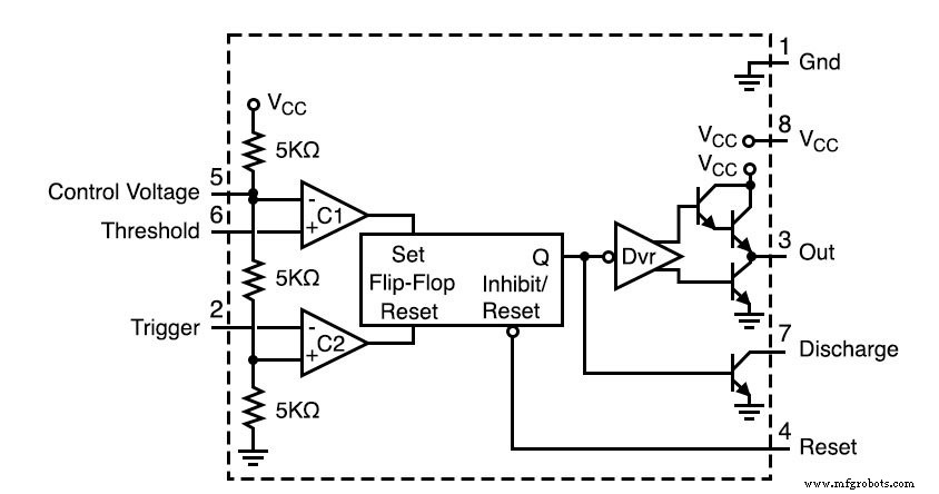
Theory of Operation
Pin 7 is a transistor that normally conducts, keeping Ct discharged. When pin 2 is pulled low, the internal comparators enable Ct to charge through Rt. When Ct reaches 2/3 VCC, the 555’s flip‑flop changes state, turning the transistor off and allowing Ct to discharge. The sequence of switching can be visualized in the accompanying waveforms.
Related Worksheets
- Timer Circuits
Industrial Technology
- The 555 Integrated Circuit: A Timeless Benchmark in Analog Design
- 555 Timer PWM DC Motor Speed Controller – Build & PCB Design Guide
- Mastering the 555 Timer IC: Principles, Block Diagrams, and Circuit Schematics
- Clap-Activated Switch: Build a Sound‑Responsive Circuit With and Without a 555 Timer
- Design a Reliable Traffic Light System Using IC 4017 Counter & 555 Timer
- 555 Timer Circuit Diagrams for 1‑15 Minute Intervals: Design, Build & Applications
- LED Roulette Circuit Using 555 Timer & CD4017 Counter – Full Diagram & Build Guide
- Build a Reliable Voltage Doubler with a 555 Timer IC – Step‑by‑Step Diagram
- Mastering the 555 Timer: A Comprehensive Guide to One-Shot Monostable Circuits
- 4047 IC Explained: Mastering Monostable & Astable Multivibrators