


555 Hysteretic Oscillator – Build a Classic RC Multivibrator
PARTS AND MATERIALS
- 1 × 9 V battery
- Battery clip (Radio Shack catalog # 270‑325)
- Mini hook clips (soldered to the battery clip, Radio Shack catalog # 270‑372)
- U1 – 555 timer IC (Radio Shack catalog # 276‑1723)
- D1 – Red LED (Radio Shack catalog # 276‑041 or equivalent)
- D2 – Green LED (Radio Shack catalog # 276‑022 or equivalent)
- R1, R2 – 1 kΩ, ¼ W resistors
- R3 – 10 Ω, ¼ W resistor
- R4 – 10 kΩ, 15‑turn potentiometer (Radio Shack catalog # 271‑343)
- C1 – 1 µF capacitor (Radio Shack catalog # 272‑1434 or equivalent)
- C2 – 100 µF capacitor (Radio Shack catalog # 272‑1028 or equivalent)
CROSS‑REFERENCES
- Lessons In Electric Circuits, Vol. 1, Ch. 16 – Voltage and Current Calculations
- Lessons In Electric Circuits, Vol. 1, Ch. 16 – Solving for Unknown Time
- Lessons In Electric Circuits, Vol. 4, Ch. 10 – Multivibrators
- Lessons In Electric Circuits, Vol. 3, Ch. 8 – Positive Feedback
LEARNING OBJECTIVES
- Understand how a Schmitt trigger drives a simple RC oscillator.
- Apply RC time‑constant concepts to control oscillation frequency.
- Explore one of several 555‑timer astable multivibrator configurations.
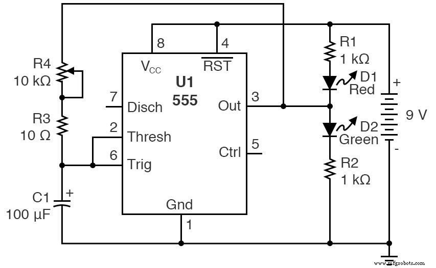
SCHEMATIC DIAGRAM
The following schematic shows one common layout for this oscillator. A second, equivalent representation is also provided below.
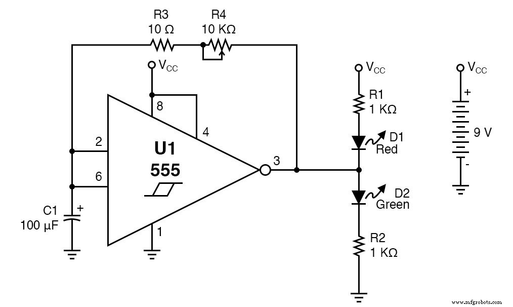
Alternatively, the circuit can be drawn with the 555 in a slightly different pin‑configuration, as illustrated below:
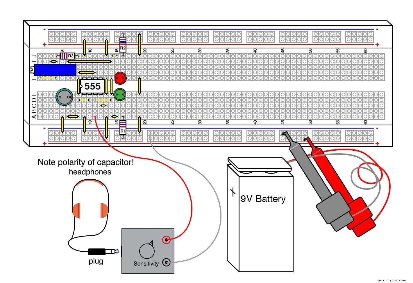
ILLUSTRATION

INSTRUCTIONS
This is one of the most fundamental RC oscillators you can build. It is straightforward, highly predictable, and ideal for demonstrating the core principles of a Schmitt‑trigger‑driven multivibrator.
Key features:
- Base frequency: ≈0.7 Hz – each LED toggles once per second.
- Adjustable frequency via the 10 kΩ potentiometer (R4). Turning it counter‑clockwise raises the frequency, eventually entering the audible range. With a 1 µF timing capacitor the frequency can climb to ~70 kHz, well into the ultrasonic band.
- LEDs provide a visual confirmation of the square‑wave output. The waveform is slightly asymmetrical because the 555’s output transistors cannot swing fully to the supply rails. Using a CMOS 555 (e.g., TLC555, Radio Shack # 276‑1718) yields a near‑50 % duty‑cycle square wave.
- R3 protects the 555 from overheating when the capacitor shorts the AC portion of the output to ground at a fresh 9 V battery. Omitting R3 can cause excessive heat; test this only for a brief moment and with caution.
To verify the frequency sweep, connect a piezoelectric speaker or the Audio Detector from Lessons In Electric Circuits, Vol. VI, Ch. 3, Sec. 12. As the potentiometer turns, you’ll hear the pitch rise in real time.
Safety note: avoid drawing large currents through the LED leads; the 555’s internal current limit protects the circuit but excessive current will damage the LEDs.
THEORY OF OPERATION
In this configuration the 555 acts as a hysteretic oscillator – a type of relaxation oscillator that alternates between two stable states. The frequency is determined by the RC network on pins 6 and 2, and the formula is:
f = 0.7 / (R × C)
Because the 555’s threshold and trigger thresholds shift with supply voltage, the oscillator’s frequency remains relatively stable across a range of voltages, provided the output rail‑to‑rail limitation is accounted for. The square‑wave asymmetry arises from the non‑ideal output swing, but the timing remains governed solely by the RC pair.
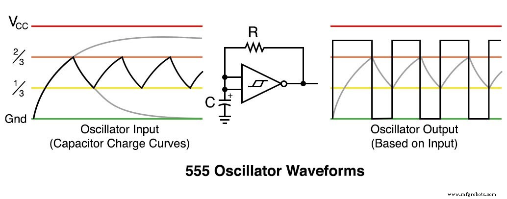
Figures below illustrate the charging and discharging curves, the initial long pulse, and the resulting asymmetric square wave.
Try out our 555 Timer Astable Circuit in our Tools section.
Industrial Technology
- Build a Low‑Frequency Astable Multivibrator Audio Oscillator with Discrete Transistors
- 555 Timer Astable Oscillator: LED Demo & Duty Cycle Exploration
- Build a High‑Performance Class B Push‑Pull Audio Amplifier with TL082 Op‑Amp
- The 555 Integrated Circuit: A Timeless Benchmark in Analog Design
- 555 Hysteretic Oscillator – Build a Classic RC Multivibrator
- Building a 555 Monostable Multivibrator: Step‑by‑Step Guide
- CMOS 555 Long‑Duration Blue LED Flasher – Practical 555 Astable Circuit Tutorial
- Crystal and Transistor Radio Circuits: From Basic Detectors to Integrated AM/FM Receivers
- The Evolution and Engineering of Radio Technology
- Build a Reliable FM Radio with SparkFun & Arduino Components