


Build a 555 Timer Schmitt Trigger: Hands‑On Circuit & Theory
Build a 555 Timer Schmitt Trigger: Hands‑On Circuit & Theory
What You’ll Need
- 1 × 9 V battery
- Battery clip (Radio Shack #270‑325)
- Mini hook clips, soldered to the battery clip (Radio Shack #270‑372)
- 1 × 10 kΩ, 15‑turn potentiometer (Radio Shack #271‑343)
- 1 × 555 timer IC (Radio Shack #276‑1723)
- 1 × red LED (Radio Shack #276‑041 or equivalent)
- 1 × green LED (Radio Shack #276‑022 or equivalent)
- 2 × 1 kΩ resistors
- 1 × DVM or VOM for voltage measurement
Learning Objectives
- Understand how a Schmitt Trigger creates hysteresis.
- Configure a 555 timer as a Schmitt Trigger.
Schematic Diagram
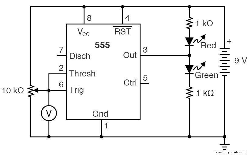
In this configuration, the 555’s internal voltage divider and comparators form a classic Schmitt Trigger, driving the LEDs via a low‑impedance output stage.
Illustration of Operation
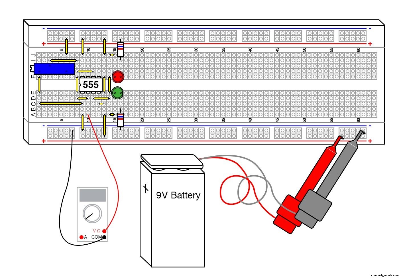
Step‑by‑Step Instructions
- Assemble the circuit on a breadboard, ensuring correct pin connections for the 555 (pin 1 = GND, pin 8 = VCC, pin 3 = OUT, pins 4 & 5 connected as per the schematic).
- Power the circuit with the 9 V battery.
- Adjust the potentiometer until the LEDs toggle state. Measure the input voltage at the 555’s threshold pin (pin 6) and note the value.
- Record the voltage and compare it to the supply voltage. Then rotate the potentiometer in the opposite direction until the LEDs toggle again, and record that voltage.
- Check how close these values are to the theoretical 1/3 VCC and 2/3 VCC thresholds.
- For further experimentation, replace the 9 V battery with a 6 V supply or two 6 V batteries in series. Observe how the thresholds shift relative to the supply.
Practical Applications
- Signal conditioning in noisy environments: the hysteresis of a Schmitt Trigger cleans up oscillations and eliminates chatter.
- Simple RC oscillators: many low‑frequency generators use a 555 in Schmitt Trigger mode.
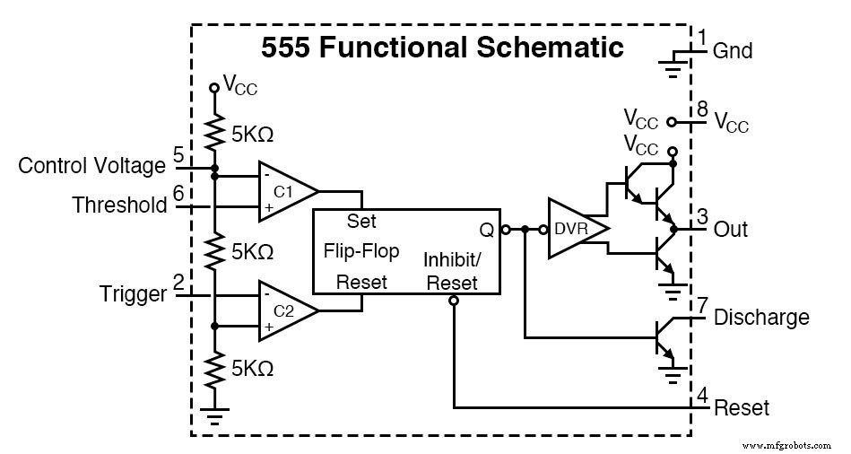
How It Works
The 555’s internal voltage divider sets two reference levels at approximately one‑third and two‑thirds of VCC. The comparators monitor the input; when the input rises above the upper reference, the flip‑flop toggles, driving the output low. When the input falls below the lower reference, the flip‑flop toggles again, driving the output high. This hysteresis ensures clean, stable transitions.
The output stage of the 555 can source or sink up to 200 mA, making it ideal for driving LEDs directly. The resistors in the LED branches keep the current within safe limits.
Although the 1 kΩ resistors are not highly precise, their matched values are sufficient because the 555’s internal circuitry dominates the threshold determination.
Industrial Technology
- 555 Timer Astable Oscillator: LED Demo & Duty Cycle Exploration
- Build a 555 Timer Schmitt Trigger: Hands‑On Circuit & Theory
- Tachogenerators: Precision Speed Measurement for Industrial Motors and Equipment
- Understanding AC Waveforms: Sine Waves, Frequency, and Oscilloscope Basics
- Mastering the 555 Timer IC: Principles, Block Diagrams, and Circuit Schematics
- Build a Reliable Voltage Doubler with a 555 Timer IC – Step‑by‑Step Diagram
- Schmitt Trigger Explained: Design, Function, and Practical Applications
- Choosing the Right Chopper: A Comprehensive Guide to Types and Applications
- Step‑by‑Step Guide to Building a Reliable DC Voltage Booster Circuit
- 78L05 Pinout Guide: Features & Wiring Instructions