


555 Timer Astable Oscillator: LED Demo & Duty Cycle Exploration
Parts & Materials
- Two 6‑V batteries
- 0.1 µF non‑polarized capacitor (Radio Shack #272‑135)
- 555 timer IC (Radio Shack #276‑1723)
- Two LEDs (Radio Shack #276‑026 or equivalent)
- 1 MΩ resistor
- 100 kΩ resistor
- Two 510 Ω resistors
- Audio detector with headphones
- Oscilloscope (recommended but not required)
An oscilloscope helps analyze waveforms, but an audio detector is a practical alternative if one isn’t available.
Cross‑References
Lessons In Electric Circuits, Vol. 4, Chapter 10: “Multivibrators.”
Learning Objectives
- Demonstrate the 555 timer as an astable multivibrator.
- Explain and calculate duty cycle.
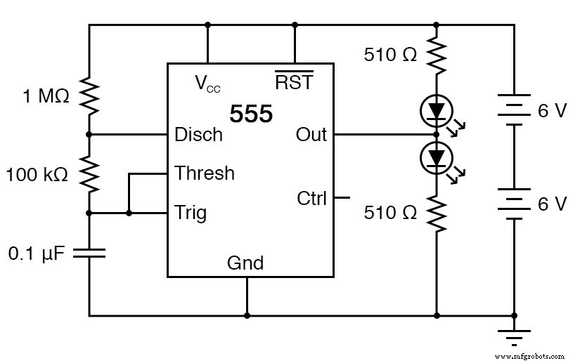
Schematic Diagram
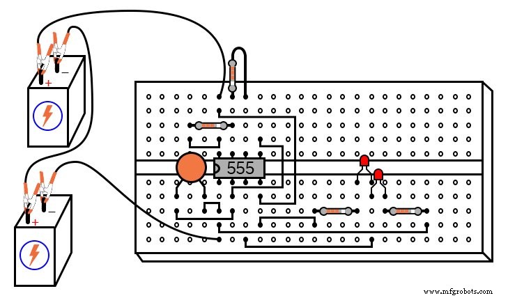
Illustration
Instructions
The 555 IC is a versatile timer that can function as an astable multivibrator. When paired with a capacitor and two resistors as shown, it oscillates freely, producing a square‑wave output that turns two LEDs on and off.
The circuit works by alternately charging and discharging the capacitor. The 555 discharges the capacitor when the voltage at the Threshold pin exceeds two‑thirds of VCC. Discharge stops when the voltage at the Trigger pin falls below one‑third of VCC, causing the capacitor voltage to oscillate between 1/3 and 2/3 VCC in a sawtooth pattern.
During the charge cycle, current flows through the series 1 MΩ and 100 kΩ resistors, creating a long time constant. When the Discharge pin is pulled low by the internal transistor, the capacitor discharges through the 100 kΩ resistor alone, yielding a much shorter time constant. The resulting square wave has a “high” period longer than the “low” period, giving a duty cycle greater than 50 %.
The 555’s Output pin is high (≈VCC) while the capacitor charges and low (≈0 V) while it discharges. This alternating signal drives the two LEDs in opposite phases, so one LED stays lit longer than the other, reflecting the duty cycle.
Use the audio detector or oscilloscope to visualize the waveform. Vary the resistor and capacitor values to observe changes in frequency and duty cycle.
Related Worksheet
- Timer Circuits Worksheet
Industrial Technology
- Build a Low‑Frequency Astable Multivibrator Audio Oscillator with Discrete Transistors
- DIY 12AX7 Vacuum Tube Audio Amplifier – Classic Sound Build
- Linear Ramp Generator with the 555 Timer – A Practical Lab Guide
- Build a 555 Timer Schmitt Trigger: Hands‑On Circuit & Theory
- 555 Hysteretic Oscillator – Build a Classic RC Multivibrator
- Practical Considerations for Selecting and Using Capacitors
- Understanding Capacitor Transient Response: Charging Dynamics, Asymptotic Behavior, and SPICE Simulation
- AC Capacitor Circuits: Capacitive Reactance, Phase Shift, and Power Behavior
- Efficient 230 VAC Power‑Outage Sensor for Raspberry Pi – Low‑Cost, Compact, and Safe
- Build a Reliable Voltage Doubler with a 555 Timer IC – Step‑by‑Step Diagram