


Designing a High‑Gain Differential Amplifier with NPN Transistors
Parts and Materials
- Two 6‑V batteries
- Two NPN transistors (2N2222 or 2N3403 recommended – see Radio Shack catalog #276‑1617 for a convenient package of fifteen)
- Two 10 kΩ single‑turn linear potentiometers (Radio Shack catalog #271‑1715)
- Two 22 kΩ resistors
- Two 10 kΩ resistors
- One 100 kΩ resistor
- One 1.5 kΩ resistor
While the exact resistor values are not critical, they have been chosen to maximize the voltage gain and give the circuit a “comparator‑like” response.
Cross‑References
See Lessons In Electric Circuits, Vol. 3, ch. 4 “Bipolar Junction Transistors” and ch. 8 “Operational Amplifiers” for foundational theory.
Learning Objectives
- Design a basic differential amplifier circuit
- Define differential and common‑mode voltages and understand their roles in amplifier operation
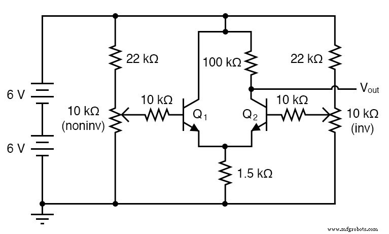
Schematic Diagram
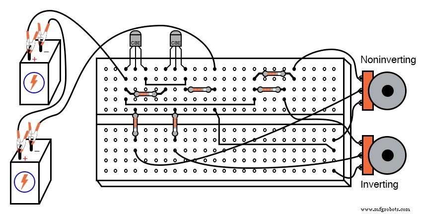
Illustration
Instructions
This configuration is the core of most op‑amp circuits: the differential pair. It is intentionally simple, providing a high‑gain, nonlinear response that functions primarily as a comparator.
The large collector‑to‑emitter resistor ratio (100 kΩ / 1.5 kΩ) gives a steep transfer characteristic. As the two input voltages converge, the output at Q₂’s collector swings quickly between the supply rails.
Note how the two potentiometers influence the output differently: one acts as a non‑inverting input, the other as an inverting input. This complementary behavior is the hallmark of a differential amplifier.
In an ideal device, the output depends solely on the voltage difference between the inputs and is immune to any common‑mode voltage. In practice, however, the circuit’s output also varies with common‑mode voltage, especially when the input range is limited by the 22 kΩ resistors.
To explore the full dynamic range, you can bypass the 22 kΩ series resistors with jumper wires, allowing each potentiometer to sweep from 0 to 12 V. The emitter resistor (1.5 kΩ) protects the transistors from thermal runaway by limiting collector current.
Related Worksheet
Industrial Technology
- Common‑Emitter Amplifier: Design, Measurement, and Feedback Techniques
- Designing a High‑Gain Multi‑Stage Common‑Emitter Amplifier with Negative Feedback
- Non‑Inverting Amplifier: Build, Test, and Master Op‑Amp Gain Control
- Understanding Amplifier Gain: Voltage, Current, and Power
- Common‑Collector Amplifier: Emitter‑Follower Fundamentals & Applications
- Single‑Ended vs. Differential Amplifiers: Design, Operation, and Applications
- The Operational Amplifier: Foundations, Features, and Key Applications
- Designing a Practical Differential Amplifier with Controlled Gain
- From Vacuum Tubes to Integrated Circuits: The Evolution of Operational Amplifier Models
- Understanding Voltage Amplifiers: How They Boost Signal Voltage