


JFET Current Regulator – Build and Test a Stable Constant‑Current Source
PARTS AND MATERIALS
- One N‑channel junction field‑effect transistor (JFET), such as the 2N3819 or J309 (Radio Shack catalog #276‑2035).
- Two 6‑V batteries.
- One 10 kΩ single‑turn, linear‑taper potentiometer (Radio Shack catalog #271‑1715).
- One 1 kΩ resistor.
- One 10 kΩ resistor.
- Three 1.5 kΩ resistors.
Important – use an N‑channel JFET, not a P‑channel device. Even identical looking packages can have different pinouts, so always verify the datasheet before wiring.
Because some manufacturers occasionally mislabel pin diagrams, double‑check each pin with a multimeter’s diode‑check function. For detailed guidance on identifying JFET terminals, see Chapter 5 of the Semiconductor Volume III series.
CROSS‑REFERENCES
- Lessons In Electric Circuits, Volume 3, Chapter 5: “Junction Field‑Effect Transistors”
- Lessons In Electric Circuits, Volume 3, Chapter 3: “Diodes and Rectifiers”
LEARNING OBJECTIVES
- Use a JFET as a precise current regulator.
- Understand the JFET’s excellent thermal stability.
SCHEMATIC DIAGRAM
ILLUSTRATION
INSTRUCTIONS
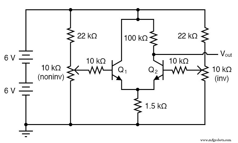
Previous chapters introduced a bipolar junction transistor (BJT) current mirror, which uses two transistors to force equal currents. The JFET current regulator replaces that pair with a single JFET, offering identical performance while simplifying the circuit.
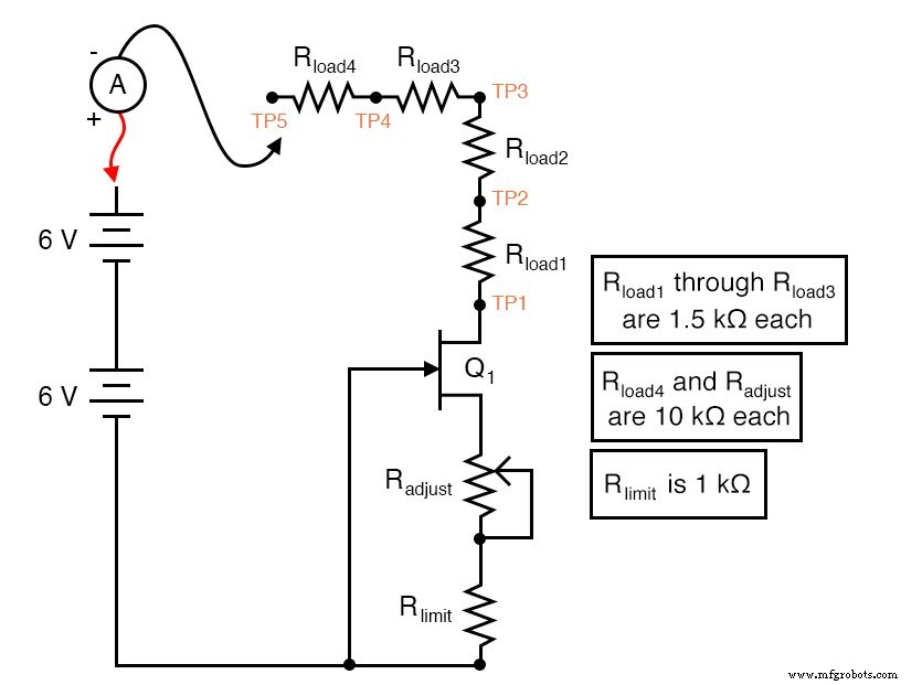
The series resistors R_adjust and R_limit set the desired current, while the load resistors and test points (TP1–TP4) demonstrate that the current remains constant regardless of load changes. Begin the experiment by placing the test probe on TP4 and sweeping the potentiometer.
You will observe a modest, adjustable current in the few‑milliamps range. Pick a convenient milliamps value, move the probe to TP3, then TP2, and finally TP1; the meter should read nearly the same each time, confirming constant‑current behavior.
To challenge the regulator, adjust the potentiometer to a different current and repeat the measurements at TP1–TP4. The current should stay stable across all four points. At TP5, which sits after a 10 kΩ resistor, the total load rises to 14.5 kΩ – a resistance that forces the JFET into saturation, causing the current to drop sharply. This illustrates the voltage‑drop limitation of the regulator.
When the regulation point is set to a lower current, the JFET can maintain regulation over a much broader load range. Try heating the transistor by hand and cooling it with a fan; the measured current will remain unchanged, showcasing the JFET’s immunity to temperature variations and its resistance to thermal runaway.
Because only one transistor is used, there is no requirement for precise matching, and the circuit is inherently immune to the temperature drift that plagues BJT mirrors.
Another application of this configuration is the “constant‑current diode.” It consists of a JFET with a fixed resistor between gate and source, protected by a series PN‑junction diode to block reverse bias. See the diagram below for the classic implementation.
COMPUTER SIMULATION
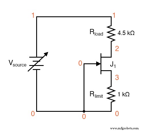
Schematic with SPICE node numbers:
Netlist (copy the following into a text file and run it in SPICE):
JFET current regulator vsource 1 0 rload 1 2 4.5k j1 2 0 3 mod1 rlimit 3 0 1k .model mod1 njf .dc vsource 6 12 0.1 .plot dc i(vsource) .end
Because SPICE does not support sweeping resistance values, the example varies the source voltage from 6 V to 12 V in 0.1‑V steps. With R_limit set to 1 kΩ, the simulated current is 291.8 µA – a figure that will differ slightly from a real circuit due to device parameter variations. Many manufacturers provide SPICE models that can be inserted into the .model line for a more accurate simulation.
RELATED WORKSHEET
- Junction Field‑Effect Transistors (JFET) Worksheet
Industrial Technology
- Hands‑On Guide to Current Dividers: Build, Measure, and Simulate with a 6 V Battery
- Voltage Regulator Experiment with a 12‑Volt Zener Diode
- Common-Emitter Amplifier Limitations: Distortion, Temperature, and High‑Frequency Challenges
- Understanding Junction Field‑Effect Transistors (JFET): Fundamentals and Applications
- Expert Guide to JFET Biasing Techniques: Achieve Stable, High‑Performance Circuits
- Decoding JFET Quirks: Common Pitfalls & How to Master Them
- Insulated‑Gate Bipolar Transistors (IGBTs): Merging FET Precision with BJT Power
- FET Testing: What It Is, How It Works, and Why You Need It
- High-Current Voltage Regulator: The Complete Expert Guide
- Understanding Current Regulators: How They Protect Your Devices