


Build a Reliable Current Mirror Circuit: Step‑by‑Step Guide
Parts and Materials
- Two NPN transistors (2N2222 or 2N3403 recommended; Radio Shack #276‑1617 offers a 15‑piece pack)
- Two 6‑V batteries
- 10 kΩ linear potentiometer (Radio Shack #271‑1715)
- Two 10 kΩ resistors
- Four 1.5 kΩ resistors
Using small‑signal transistors lets you observe the subtle “thermal runaway” effect at low currents. Any pair of identical NPNs will work, but check the datasheet for pin‑out consistency—mislabelled packages can mislead.
Verify pin assignments with a multimeter’s diode‑check mode; chapter 4 of the Semiconductor Volume III series covers this in detail.
Learning Objectives
- Construct a current‑mirror circuit
- Understand its current‑regulation limits
- Explore temperature dependence of BJTs
- Experience controlled thermal runaway
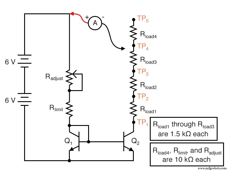
Schematic Diagram
Illustration
Instructions
A current mirror functions as a simple adjustable current regulator. The current is set by a single resistance, making it a widely used, low‑cost solution.
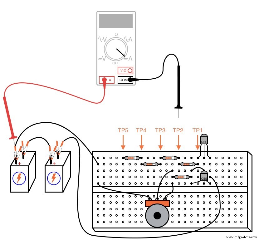
Build the circuit exactly as shown. You’ll need one extra 1.5 kΩ resistor for the final phase of the experiment.
The potentiometer controls the collector current of Q1, which behaves like a diode. Matching the base‑emitter junctions of Q1 and Q2 ensures that the same voltage drives both transistors, so their collector currents mirror each other.
Because the base currents are equal and the transistors are matched, Q2 automatically adjusts its collector‑emitter voltage to maintain the same collector current, regardless of load resistance.
To test this, the load on Q2 is connected to an ammeter. Five test points (TP1–TP5) allow you to change the load resistance from near‑zero to ~14.5 kΩ quickly.
Begin by placing the ammeter’s black probe on TP4 and sweep the potentiometer. Record the current. Move the probe to TP3, TP2, and TP1, noting how the current remains stable. Then repeat with the potentiometer set to a different current. The current should remain nearly constant until the load resistance approaches TP5, where the current drops because Q2 can no longer supply the same current at that high resistance.
These results illustrate the regulator’s practical limits. The device can only supply a fixed current up to a certain load resistance; beyond that, it saturates.
Temperature is critical. If one transistor overheats, its base‑emitter voltage changes, breaking the mirror. Keep the two transistors at the same temperature—gluing them back‑to‑back is common practice.
To observe the effect, heat one transistor by hand; the load current will increase. Cool it and heat the other transistor; the current will change accordingly. Finally, allow one transistor to overheat by setting the potentiometer to ~10 mA, then increasing it to 30 mA. Observe the rise in current without adjusting the potentiometer—this is thermal runaway.
Computer Simulation
Use SPICE to model the circuit. Insert the following netlist into a text file:
Current mirror v1 1 0 vammeter 1 3 dc 0 rlimit 1 2 10k rload 3 4 3k q1 2 2 0 mod1 q2 4 2 0 mod1 .model mod1 npn bf=100 .dc v1 12 12 1 .print dc i(vammeter) .end
Vammeter is a zero‑voltage source that measures the load current. Adjust Rload to see the regulator’s performance; with Rlimit at 10 kΩ and 12 V supply, the simulated current is 1.1 mA over a wide resistance range.
Related Worksheets
- Regulated Power Sources Worksheet
- Differential Transistor Amplifiers Worksheet
Industrial Technology
- Bipolar Transistors: Symbols, Types, and Applications
- Hybrid Transistor Design: IGFET‑BJT Combo for High Gain and Low Drop
- Understanding Current Mirrors in Bipolar Junction Transistor Circuits
- Understanding Electrical Resistance and Circuit Safety
- Build Your Own LED Flashlight: Step‑by‑Step Circuit Guide
- Create a Reliable Continuity Tester Circuit – Easy DIY Guide
- Designing a Reliable Heat Sensor Circuit: Operation Explained & Step‑by‑Step Build Guide
- Building a Crystal Oscillator Circuit: A Practical Guide for Engineers
- Step‑by‑Step Guide to Building a Reliable DC Voltage Booster Circuit
- Build a Pulsing LED Circuit: Step‑by‑Step Guide to Stunning Light Effects