


Understanding Electrical Resistance and Circuit Safety
The circuit discussed earlier is far from practical and can be hazardous. Directly connecting the poles of a voltage source with a single wire creates a short circuit, allowing enormous current to flow. The resulting energy release—usually in the form of heat—can be dramatic and dangerous. Practical electrical design seeks to harness this energy safely and efficiently.
Current Flow Through a Lamp Filament
A common application of electric current is lighting. The simplest lamp consists of a thin metal filament inside a glass bulb that glows white‑hot when enough current passes through it. Like a battery, the lamp has two conductive terminals—one for current entry and one for exit. When connected to a voltage source, the circuit resembles the following:
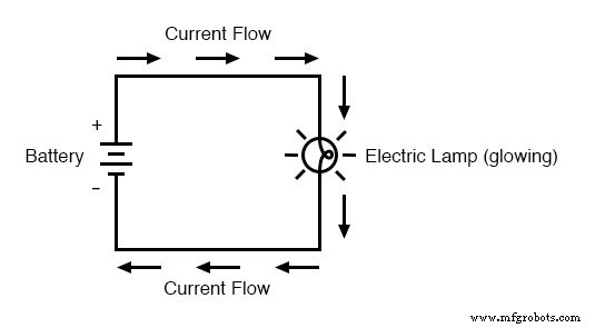
The filament offers more resistance than a thick wire, limiting the current for a given voltage. Resistance depends on material, cross‑section, and temperature. As current encounters this opposition, electrical friction converts energy into heat. The filament’s concentrated resistance generates enough heat to cause it to glow white‑hot, producing light, while the connecting wires—having much lower resistance—remain nearly cool even under the same current. If the circuit is broken at any point, the lamp stops glowing:
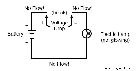
With no current flow, the battery’s full voltage remains across the break, waiting for a new connection to restore the circuit. This state is known as an open circuit. A single discontinuity prevents current flow throughout the entire circuit. Reestablishing continuity turns the circuit into a closed circuit.
Switching Lamps On and Off
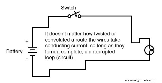
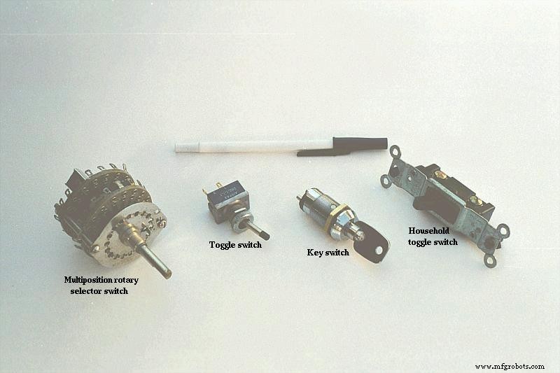
The ability to interrupt a circuit’s continuity forms the basis for switching lamps. A device that intentionally breaks continuity—called a switch—is mounted at a convenient location and controls the lamp from a distance. A typical wall switch consists of two conductive contacts, usually metal, brought together by a lever or button. When the contacts touch, current flows; when they separate, the air gap isolates the circuit, halting current flow.
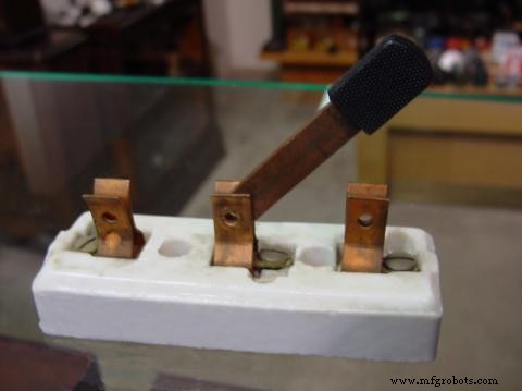
The Knife Switch
A classic illustration of a switch is the knife switch, a conductive lever pivoting on a hinge to touch stationary contacts. The example below shows a knife switch on a porcelain base with a copper blade and contacts, and a plastic handle for user insulation:

Another variant has a single blade but two stationary contacts, enabling the switch to control multiple circuits:
While knife switches effectively demonstrate basic switching principles, they pose safety risks in high‑power circuits. Exposed conductors can touch the circuit unintentionally, and sparking between moving and stationary contacts can ignite nearby flammable materials. Modern switches enclose contacts within insulated housings to mitigate these hazards, as shown in the following image:
Open and Closed Circuits
In electrical terminology, a switch is closed when its contacts are touching, allowing current to flow, and open when the contacts are separated, preventing current. This terminology can be counterintuitive, as “open” in everyday language implies passage, whereas in circuits it means no flow. Understanding these definitions is essential for interpreting circuit behavior.
Review
- Resistance measures opposition to electric current.
- A short circuit offers little resistance, potentially delivering high currents that generate significant heat—dangerous with high voltage sources.
- An open circuit has a broken path, stopping current flow.
- A closed circuit is continuous, permitting current flow.
- A switch controls circuit continuity under controlled conditions.
- The terms open and closed apply to both entire circuits and individual switches.
Related Worksheets
- Switches
- Resistor
- Voltage, Current, and Resistance
Try out our Resistance Calculator in the Tools section.
Industrial Technology
- Precision 4‑Wire Resistance Measurement: The Kelvin Method
- Build a Reliable Current Mirror Circuit: Step‑by‑Step Guide
- Why Grounding Matters: Preventing Shock from a Single Wire
- Understanding Ohm’s Law and the Real Risks of Electrical Shock
- How Ammeter Resistance Affects Circuit Measurements: Insights & Solutions
- Precision 4‑Wire Kelvin Resistance Measurement: Eliminating Wire‑Resistance Errors
- Series RC Circuit Analysis: Impedance, Phase Relationships, and SPICE Validation
- Understanding Resistance, Reactance, and Impedance in AC Circuits
- How Current Limiting Circuits Protect Electronics & Power Supplies
- Building a TDCS Circuit: Step‑by‑Step Guide to Brain Stimulation