


Series RC Circuit Analysis: Impedance, Phase Relationships, and SPICE Validation
In the previous section we explored simple resistor‑only and capacitor‑only AC circuits. This article shows how combining these elements in series transforms the behavior.
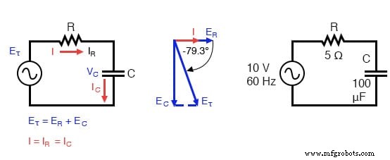
Series capacitor circuit: voltage lags current by 0° to 90°.
Impedance Calculation
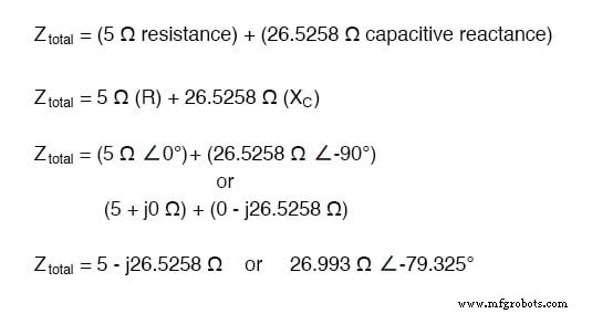
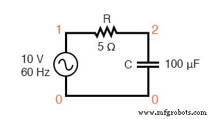
The resistor provides a constant 5 Ω of resistance to AC current at any frequency, while the capacitor offers 26.5258 Ω of reactance at 60 Hz.
Because the resistor’s impedance is the real number 5 Ω ∠ 0° (or 5 + j0 Ω) and the capacitor’s impedance is the imaginary number 26.5258 Ω ∠ –90° (or 0 – j26.5258 Ω), the combined opposition to current is the complex sum of these two values.
This complex opposition is called impedance, denoted Z, and measured in ohms, just like resistance and reactance. For the circuit shown, the total impedance is:
Impedance relates voltage and current in the same way resistance does in DC, but it captures both magnitude and phase:
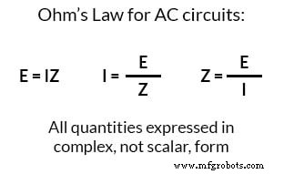
This form of Ohm’s Law (E = IZ) is far more comprehensive than the DC version (E = IR). Any resistance or reactance—whether separate or combined in series or parallel—can and should be represented as a single impedance.
Current Calculation
To determine current, we first set the source voltage phase angle to zero, the standard reference point. Resistive and capacitive impedances always have phase angles of 0° and –90°, respectively, independent of the source.
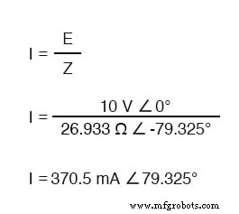
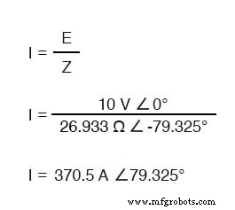
The current leads the source voltage by 79.325°, less than the 90° lead seen in a purely capacitive circuit.
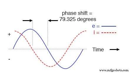
Voltage lags current (current leads voltage) in a series R‑C circuit.
Table Method
As with DC analysis, organizing values in a table streamlines AC calculations. For this series circuit, we list the known quantities and propagate them through the analysis:
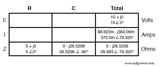
Since current is common to all series elements, the total current column can be distributed to each component. Applying Ohm’s Law vertically yields the voltage across the resistor and capacitor:
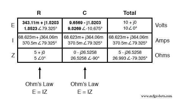
The resistor’s voltage shares the same phase as the current, confirming that E and I are in phase for that element. The capacitor’s voltage, at –10.675°, is exactly 90° behind the circuit current, as expected for a capacitive load.
Calculations Using SPICE
To verify the analytical results, we simulate the circuit in SPICE:
SPICE circuit: R‑C.
ac r-c circuit
 v1 1 0 ac 10 sin
 r1 1 2 5
 c1 2 0 100u
 .ac lin 1 60 60
 .print ac v(1,2) v(2,0) i(v1)
 .print ac vp(1,2) vp(2,0) ip(v1)
 .end
 freq            v(1,2)       v(2)       i(v1)
 6.000E+01       1.852E+00       9.827E+00       3.705E-01

 freq            vp(1,2)       vp(2)       ip(v1)
 6.000E+01       7.933E+01       -1.067E+01      -1.007E+02
SPICE reports the current phase as –100.7°, which corresponds to +79.3° once the 180° offset is removed, matching the analytical 79.325° result. Note that measured voltages and currents correspond to the magnitude (polar form) of the calculated phasors, not the rectangular components.
For instance, a voltmeter reading across the resistor would display 1.852 V, not the 343.11 mV (real) or 1.8203 V (imaginary) rectangular values. While rectangular notation aids arithmetic, polar form directly represents real‑world measurements.
Impedance of a series R‑C circuit can be computed from resistance (R) and capacitive reactance (XC). Using E = IR, E = IXC, and E = IZ, the voltage phasor diagram parallels the impedance diagram.
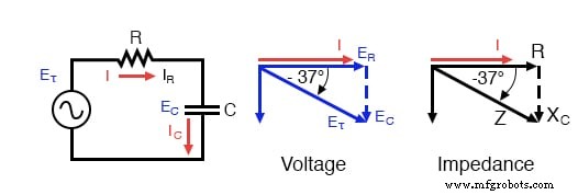
Series R‑C circuit impedance phasor diagram.
Example: A 40 Ω resistor in series with an 88.42 µF capacitor at 60 Hz. Find the impedance.
 XC = 1/(2πfC)
 XC = 1/(2π·60·88.42×10‑6)
 XC = 30 Ω
 Z = R - jXC
 Z = 40 - j30
 |Z| = sqrt(40² + (-30)²) = 50 Ω
 ∠Z = arctan(-30/40) = -36.87°
 Z = 40 - j30 = 50∠-36.87°
Review:
- Impedance (Z) is the total opposition to AC current and equals the complex sum of resistance and reactance.
- In series circuits, impedances add exactly as resistances do: Ztotal = Z1 + Z2 + … + Zn.
- Impedances are added in complex form regardless of component type.
- A purely resistive impedance has a phase angle of 0° (ZR = R ∠ 0°).
- A purely capacitive impedance has a phase angle of –90° (ZC = XC ∠ –90°).
- AC Ohm’s Law: E = IZ; I = E/Z; Z = E/I.
- When resistors and capacitors coexist, the total impedance phase lies between 0° and –90°.
Related Worksheets:
Industrial Technology
- Key Rules for Series Circuits: Current, Resistance, and Voltage
- Advanced Motor Control Circuits: Latching, Stop, and Time‑Delay Techniques
- Complementary NPN/PNP Audio Amplifier Circuit – Direct Coupling for Moderate Power
- Understanding Electrical Resistance and Circuit Safety
- Understanding Series and Parallel Circuits: How They Work and Why They Matter
- Understanding Simple Series Circuits: Key Principles and Practical Examples
- Analyzing Complex RC Circuits Using Thevenin’s Theorem
- Analyzing Series Resistor‑Inductor AC Circuits: Impedance, Phase, and SPICE Verification
- Parallel Resistor–Capacitor AC Circuits: Analysis, Impedance, and Ohm’s Law
- How Current Limiting Circuits Protect Electronics & Power Supplies