


Analyzing Series Resistor‑Inductor AC Circuits: Impedance, Phase, and SPICE Verification
In the previous section we examined simple resistor‑only and inductor‑only AC circuits. Now we combine the two elements in series to explore how resistance and reactance interact and shape the overall circuit behavior.
Series Resistor‑Inductor Circuit Example
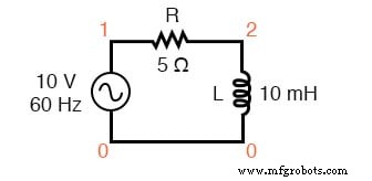
Consider the following schematic:
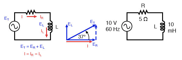
Series resistor‑inductor circuit: the current lags the applied voltage by 0° to 90°.
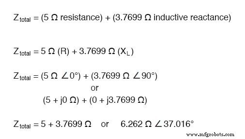
The resistor provides a fixed resistance of 5 Ω across all frequencies, while the inductor contributes an inductive reactance of 3.7699 Ω at 60 Hz. Because the resistor’s opposition is purely real (5 Ω ∠ 0°) and the inductor’s opposition is purely imaginary (3.7699 Ω ∠ 90°), their combined effect is a complex sum that we refer to as impedance.
Impedance, denoted Z, is measured in ohms just like resistance and reactance, but it encapsulates both magnitude and phase information.
The total circuit impedance is therefore:
Resistance and Ohm’s Law in AC
Impedance relates voltage and current just as resistance does in DC circuits:
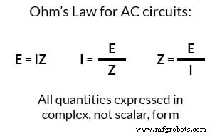
This generalization of Ohm’s Law applies to any AC network, whether the elements are resistive, inductive, or a combination thereof. For series or parallel arrangements, we treat the entire set of components as a single impedance.
To solve for current, we first establish a phase reference for the voltage source, which is conventionally taken as 0°. The resistor’s voltage remains in phase with its current (0° shift), while the inductor’s voltage leads its current by +90°.
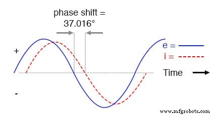
In this mixed circuit, the overall current lags the supply voltage by only 37.016°, far less than the 90° lag seen in a purely inductive circuit.
Current lags voltage in a series L‑R circuit.
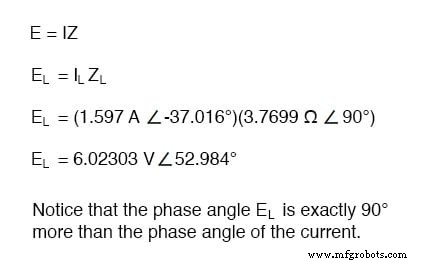
Mathematically, the voltage across each component reflects its individual phase relationship with the current:
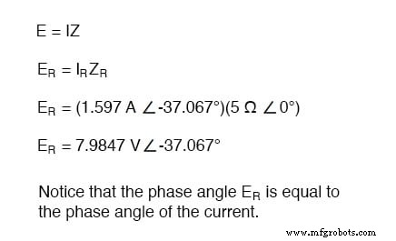
The resistor’s voltage has the same phase as the current, confirming they are in phase. Conversely, the inductor’s voltage is 90° out of phase with its current:
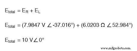
Kirchhoff’s Voltage Law Revisited
Kirchhoff’s Voltage Law (KVL) holds for complex quantities as well:
Verification with SPICE
We validated the analytical results using SPICE:
Spice circuit: R‑L
v1 1 0 ac 10 sin
r1 1 2 5
l1 2 0 10m
.ac lin 1 60 60
.print ac v(1,2) v(2,0) i(v1)
.print ac vp(1,2) vp(2,0) ip(v1)
.end
freq            v(1,2)       v(2)       i(v1)
6.000E+01       7.985E+00    6.020E+00  1.597E+00

freq            vp(1,2)       vp(2)       ip(v1)
6.000E+01      -3.702E+01    5.298E+01   1.430E+00
SPICE reports current with a 180° offset relative to the source, a convention that does not affect the physical interpretation of the results. The phase angles for resistor and inductor voltages match our analytical predictions (-37.02° and 52.98°).
To streamline the calculation process, we employ a tabular method. The table lists each component’s impedance in both rectangular and polar forms, then sums them to find the total impedance. Using Ohm’s Law (I = E/Z), we compute the common series current and subsequently determine each voltage drop.
Below is a schematic of the table approach (simplified for brevity):
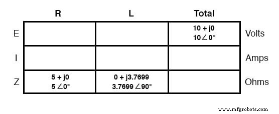
Because the circuit is series, the same current flows through every element. Once we have the total current, we multiply it by each component’s impedance to obtain the corresponding voltage drop. This method mirrors the DC approach but requires complex arithmetic.
All quantities in AC analysis must be represented as complex numbers; neglecting phase leads to incorrect results. Once phase is properly accounted for, the analysis techniques are essentially identical to DC circuit analysis.
Instrument readings, such as voltmeter or ammeter values, correspond to the magnitude of the complex phasor (polar notation). For example, a voltmeter across the resistor would read 7.9847 V, not the rectangular components 6.3756 V + j4.8071 V.
In summary:
- Impedance (Z) is the complex sum of resistance (R) and reactance (X).
- Series impedances add algebraically: Z_total = Z₁ + Z₂ + … + Zₙ.
- A purely resistive impedance has a phase of 0°, a purely inductive impedance a phase of +90°.
- Ohm’s Law for AC: E = IZ, I = E/Z, Z = E/I.
- In a mixed R‑L circuit, the impedance phase lies between 0° and +90°, and the current phase between 0° and –90°.
- Series AC circuits obey the same rules as DC: uniform current, additive voltage drops, additive impedances.
Example: A 40 Ω resistor in series with a 79.58 mH inductor at 60 Hz.
- XL = 2πfL = 30 Ω.
- Z = R + jXL = 40 + j30 Ω.
- |Z| = √(40² + 30²) = 50 Ω.
- ∠Z = arctan(30/40) = 36.87°.
- Z = 50 Ω ∠ 36.87°.
Review
- Impedance quantifies total opposition to current as a complex number.
- Series impedances add directly; calculations must be performed in complex form.
- Purely resistive or inductive components have fixed phase angles.
- Ohm’s Law generalizes to AC circuits via complex impedance.
- Mixed circuits exhibit intermediate phase angles.
- Series AC circuits mirror DC fundamentals.
Related Worksheets
- Inductors Worksheet
- Resistance, Reactance, and Impedance Worksheet
- Inductive Reactance Worksheet
Industrial Technology
- Exploring Voltage Addition with Series Battery Connections
- Power Supply Circuits: Types, Design Principles, and Performance
- Understanding Power in Electric Circuits: Measurement & Significance
- Understanding Simple Series Circuits: Key Principles and Practical Examples
- Voltage Divider Circuits: Mastering Series Resistor Analysis & Potentiometers
- Understanding AC Inductor Circuits: Reactance, Phase Shift, and Power Dynamics
- Analyzing Parallel Resistor–Inductor AC Circuits: A Practical Guide
- Pure Resistive AC Circuits: Voltage and Current In Phase
- AC Capacitor Circuits: Capacitive Reactance, Phase Shift, and Power Behavior
- Series RC Circuit Analysis: Impedance, Phase Relationships, and SPICE Validation