


Voltage Divider Circuits: Mastering Series Resistor Analysis & Potentiometers
Explore how a simple series circuit splits voltage across its resistors, and learn how to predict these drops using the voltage‑divider formula.
Analyzing a Series Circuit
Consider the following example:
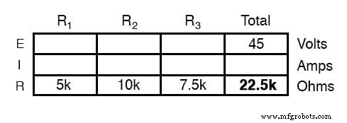
With resistors R1 = 4 kΩ and R2 = 8 kΩ, the total resistance is simply the sum:
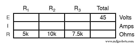
Determine the Total Circuit Resistance
Using Ohm’s Law (I = E/R), the current through the entire loop is
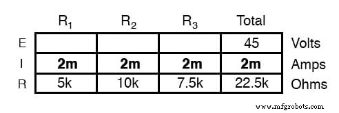
Use Ohm’s Law to Calculate Current
For a source voltage of 10 V, the loop current is 2 mA. The voltage drop across each resistor follows V = IR:
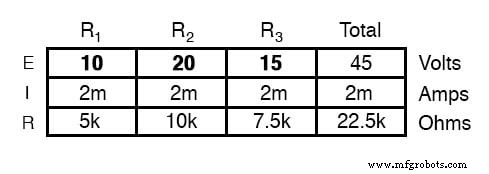
Notice that the drop across R2 is twice that of R1, mirroring their resistance ratio.
Solving for Voltage Drop Ratios
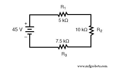
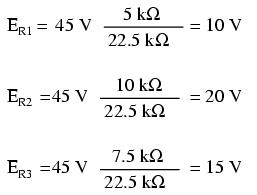
Changing the supply voltage does not alter the proportional drops:
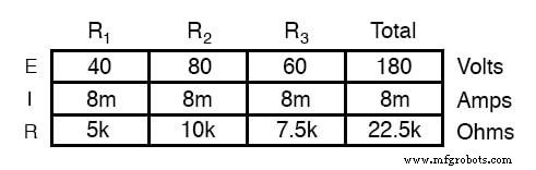
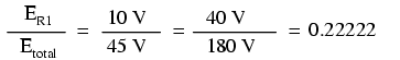
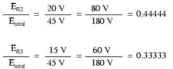
Even when the battery voltage jumps from 45 V to 180 V, the fraction of the total voltage that each resistor receives remains constant.
Voltage Divider Formula
The key insight is that
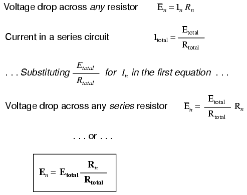
This concise relation allows quick prediction of any resistor’s drop without computing the current explicitly.
Example of Using the Voltage Divider Formula
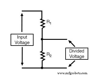
Voltage‑Dividing Components
Voltage dividers are essential in metering circuits, where precise fractions of a supply voltage are required.
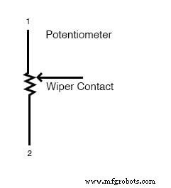
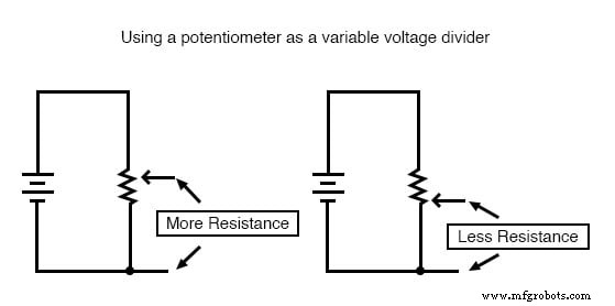
Potentiometers as Variable Dividers
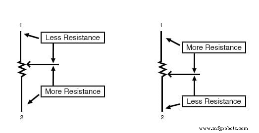
A potentiometer is a three‑terminal resistor with a sliding contact (wiper). Moving the wiper changes the effective resistance between the outer terminals, enabling a variable voltage tap.
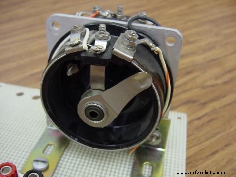
Rotary vs. Linear Potentiometers
Linear Potentiometers
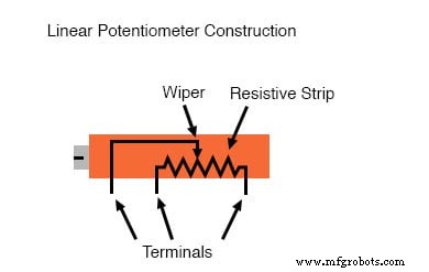
Linear units may be actuated by a lever or a fine‑tuning turn‑screw, often labeled as “trimpots” for precision trimming.
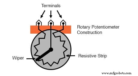
Rotary Potentiometer
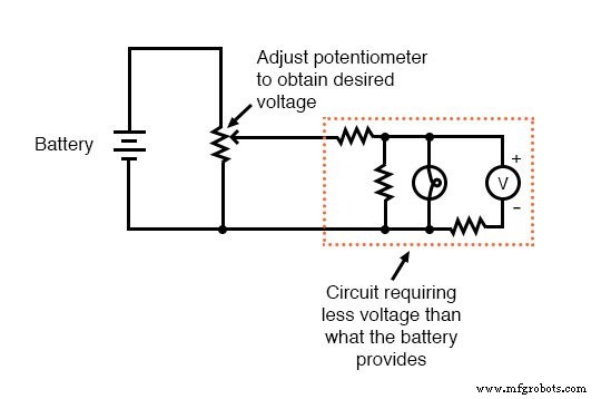
Adjusting Potentiometers in Circuits
With a fixed voltage applied across the outer terminals, the wiper taps a proportional fraction of that voltage. The fraction depends solely on the wiper’s position, not on the supply magnitude.
Practical Use of Potentiometers
Potentiometers are invaluable for deriving a lower voltage from a higher supply. For instance, a 12 V battery can be paired with a potentiometer to generate 5 V for a microcontroller.
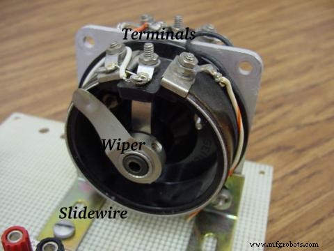
Common Potentiometer Types
Below are typical small units used in hobby and educational projects:
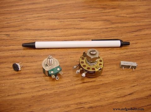
And specialized variants:
Review
- Series circuits proportionally divide the supply voltage based on resistance: En = Etotal (Rn / Rtotal)
- A potentiometer is a three‑terminal, variable‑resistance element widely used as an adjustable voltage divider.
Related Worksheets
- Voltage Divider Circuits Worksheet
Industrial Technology
- Voltage Divider Lab: Design, Measurement, and Kirchhoff’s Voltage Law Verification
- Building a Precise Voltage Divider with a Potentiometer
- Sensitive Voltage Detector: Build a High‑Sensitivity Audio Signal Detector
- Power Supply Circuits: Types, Design Principles, and Performance
- Understanding Power in Electric Circuits: Measurement & Significance
- Parallel Circuits Explained: Voltage, Current, and Resistance Principles
- Current Divider Circuits: Theory, Formula, and Practical Applications
- Understanding AC Inductor Circuits: Reactance, Phase Shift, and Power Dynamics
- AC Capacitor Circuits: Capacitive Reactance, Phase Shift, and Power Behavior
- Master Voltage Divider Rule (VDR): Step‑by‑Step Examples for Resistor, Inductor, and Capacitor Circuits