


Building a Precise Voltage Divider with a Potentiometer
PARTS AND MATERIALS
- Two 6‑volt batteries
- Carbon pencil “lead” (graphite‑clay rod) for a mechanical‑style pencil
- Single‑turn, 5 kΩ – 50 kΩ, linear‑taper potentiometer (Radio Shack # 271‑1714 – 271‑1716)
- Multi‑turn, 1 kΩ – 20 kΩ, linear‑taper potentiometer (Radio Shack # 271‑342, 271‑343, 900‑8583, 900‑8587 – 900‑8590)
INTRODUCTION
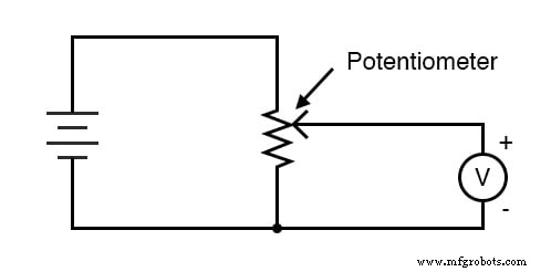
A potentiometer functions as a variable voltage divider. By turning its shaft or sliding its control, you set the ratio between two output voltages.
Potentiometers are available in panel‑mount and breadboard (PCB) configurations. For this experiment any style will work, but a linear potentiometer is preferred because its resistance changes proportionally with position. Audio‑taper (logarithmic) potentiometers, often salvaged from radios, exhibit a non‑linear relationship and are less suitable for precise voltage division.
CROSS‑REFERENCES
Lessons In Electric Circuits, Volume 1, Chapter 6: “Divider Circuits and Kirchhoff’s Laws.”
LEARNING OBJECTIVES
- Use a voltmeter to read voltage across a resistor network.
- Use an ohmmeter to verify resistor values.
- Design and analyze a voltage divider.
- Demonstrate how voltages add in series.
SCHEMATIC DIAGRAM
ILLUSTRATION
INSTRUCTIONS
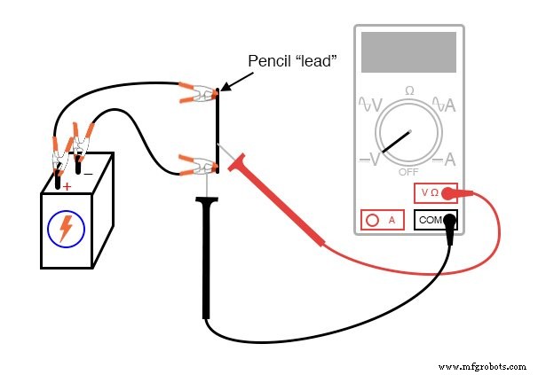
Begin with the graphite pencil “lead” as a makeshift resistor. Connect both ends of the rod to a 6‑volt battery using alligator clips. Attach a voltmeter across the rod and move the red probe along its length. Observe how the reading changes; the maximum occurs when the probe is at the midpoint, dividing the rod into two equal resistances.
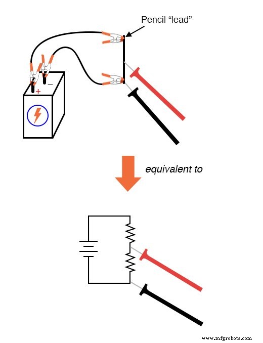
Next, re‑wire the voltmeter to measure only the upper segment of the rod. Move the black probe along the rod and note the voltage drop. The highest reading appears when the probe is near the positive terminal, confirming that the voltage drop is largest across the longest segment.
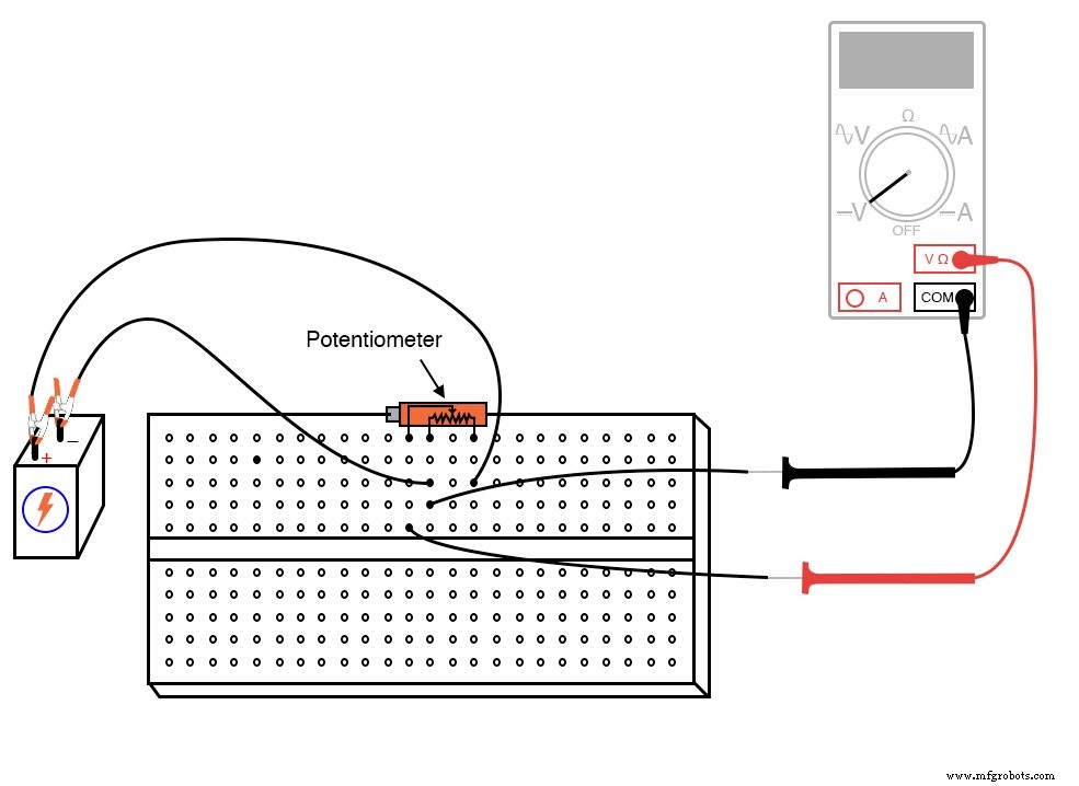
Manufactured potentiometers encapsulate a resistive strip in a housing, with a wiper that slides or rotates along the strip. A rotary potentiometer often uses a spiral track, requiring several turns to traverse the full range; this is ideal for fine adjustment. Linear potentiometers move the wiper linearly along the strip and may employ a sliding or screw mechanism for multi‑turn precision.
When setting up a real potentiometer, first measure the battery voltage. Then, with the potentiometer connected, measure the voltage between the wiper and the negative end of the battery. Turn the shaft until the voltmeter reads exactly one‑third of the total voltage (≈ 2 V for a 6‑V battery). Finally, repeat the measurement with two batteries in series (≈ 12 V). The ratio of the wiper voltage to the total voltage should remain 1 : 3, confirming the divider’s accuracy.
RELATED WORKSHEETS
- Potentiometers Worksheet
- Voltage Divider Circuits Worksheet
- Simultaneous Equations for Circuit Analysis Worksheet
Industrial Technology
- Exploring Voltage Addition with Series Battery Connections
- Voltage Divider Lab: Design, Measurement, and Kirchhoff’s Voltage Law Verification
- Hands‑On Guide to Current Dividers: Build, Measure, and Simulate with a 6 V Battery
- Build a Precise, Low‑Cost Compound Potentiometer Circuit
- Precision Op‑Amp Integrator Lab: Bias‑Current Compensation & Analog Computation
- Voltage Divider Circuits: Mastering Series Resistor Analysis & Potentiometers
- Tachogenerators: Precision Speed Measurement for Industrial Motors and Equipment
- Understanding AC Waveforms: Sine Waves, Frequency, and Oscilloscope Basics
- Master Voltage Divider Rule (VDR): Step‑by‑Step Examples for Resistor, Inductor, and Capacitor Circuits
- Mastering Capacitive Voltage Dividers: Design, Theory, and Practical Applications