


Hands‑On Guide to Current Dividers: Build, Measure, and Simulate with a 6 V Battery
Parts and Materials
- Calculator or pencil & paper for calculations
- 6‑volt battery (rechargeable or fresh)
- Resistors ranging from 1 kΩ to 100 kΩ
Cross‑References
Lessons In Electric Circuits, Volume 1, Chapter 6: “Divider Circuits and Kirchhoff’s Laws.”
Learning Objectives
- Accurately use a voltmeter, ammeter, and ohmmeter.
- Apply Ohm’s Law (I = E/R) and Kirchhoff’s Current Law (KCL).
- Design a current‑divider network.
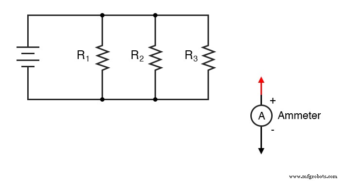
Schematic Diagram
Illustration
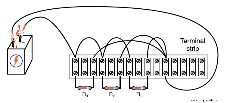
Note: The top screw of the rightmost lug is used to join three wires for demonstration purposes only; it does not reflect best practice in professional assemblies.
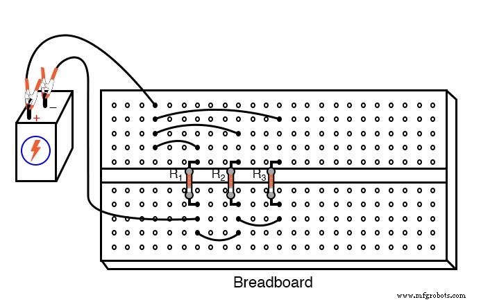
Instructions
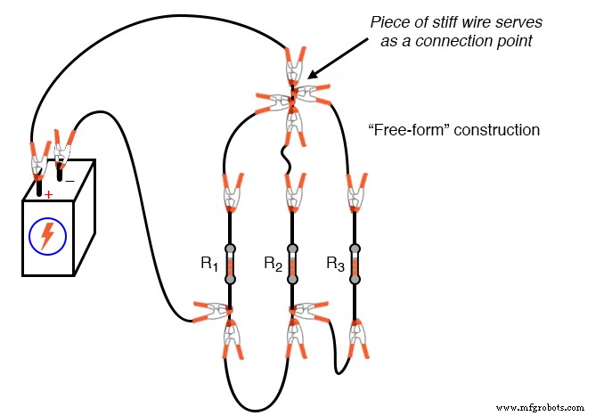
Experiment with three construction methods—breadboard, terminal strip, and free‑form—to understand their respective advantages and disadvantages.
- Select three resistors from your assortment. Measure each with an ohmmeter, and record the values.
- Connect the resistors in parallel between the positive and negative terminals of the 6 V battery, as shown.
- Measure the battery voltage with a voltmeter once the resistors are connected. Record this value; it may differ slightly from the no‑load voltage.
- Measure the voltage across each resistor. In a parallel circuit, the voltage across all components is identical.
- Use Ohm’s Law to calculate the current through each resistor: I = V/R. Verify these values by measuring current with a digital ammeter.
- Place the red probe on the junction of the positive ends of all resistors.
- Lift one resistor’s wire and connect the black probe to that wire to read its current.
- Measure the total circuit current by connecting the ammeter’s black probe to the battery’s positive lead while keeping the red probe on the same junction. The reading should be positive.
- Add the three branch currents algebraically to the total current. According to Kirchhoff’s Current Law, the sum should equal zero.
- Disconnect the battery and measure the resistance across the parallel network with an ohmmeter. The reading will be lower than any individual resistor value, and it will be the same regardless of which resistor terminals you use.
- Divide the measured battery voltage by the total resistance to compute the total current; it should closely match the measured total current.
- Note that each branch current is a fraction of the total current, proportional to the ratio of the total resistance to the individual resistance.
Computer Simulation
Schematic with SPICE node numbers:
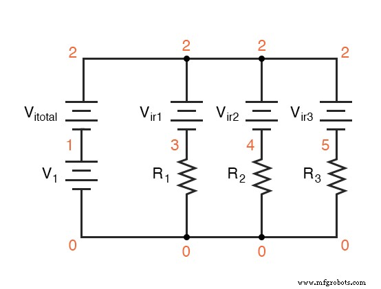
In SPICE, ammeters are represented by zero‑voltage sources. The following netlist can be saved as a text file and run in any SPICE‑compatible simulator:
Current divider
v1 1 0
r1 3 0 2k
r2 4 0 3k
r3 5 0 5k
vitotal 2 1 dc 0
vir1 2 3 dc 0
vir2 2 4 dc 0
vir3 2 5 dc 0
.dc v1 6 6 1
.print dc i(vitotal) i(vir1) i(vir2) i(vir3)
.end
Running the simulation outputs four currents: the total (negative) and the three branch currents (positive). Their algebraic sum is zero, confirming Kirchhoff’s Current Law.
Related Worksheets
Industrial Technology
- Voltage Divider Lab: Design, Measurement, and Kirchhoff’s Voltage Law Verification
- Common-Emitter Amplifier Limitations: Distortion, Temperature, and High‑Frequency Challenges
- Insulated‑Gate Bipolar Transistors (IGBTs): Merging FET Precision with BJT Power
- DIAC: The Bidirectional Trigger for AC Thyristors
- Understanding Electrical Resistance and Circuit Safety
- Current Divider Circuits: Theory, Formula, and Practical Applications
- Understanding Meter Design: From Classic Galvanometers to Modern Digital Displays
- Current Signal Systems: The 4‑20 mA Loop Explained
- Branch Current Method: A Step‑by‑Step Guide to Solving Circuit Networks
- Norton’s Theorem: Simplifying Linear Circuits with Current Sources and Parallel Resistance