


Voltage Divider Lab: Design, Measurement, and Kirchhoff’s Voltage Law Verification
PARTS AND MATERIALS
- Calculator (or pencil and paper for arithmetic)
- 6‑volt battery
- Resistors ranging from 1 kΩ to 100 kΩ
For precise readings, we confine resistor values to the 1 kΩ–100 kΩ band. Extremely low resistances can cause the ammeter’s internal resistance to distort current measurements, while very high resistances may load the voltmeter and alter the effective circuit resistance.
CROSS‑REFERENCES
Lessons In Electric Circuits, Volume 1, chapter 6: “Divider Circuits and Kirchhoff’s Laws.”
LEARNING OBJECTIVES
- Use a voltmeter, ammeter, and ohmmeter
- Apply Ohm’s Law
- Apply Kirchhoff’s Voltage Law (KVL)
- Design a voltage divider
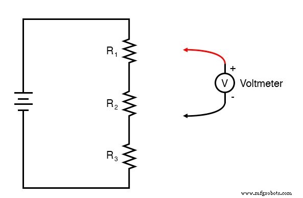
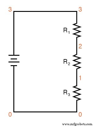
SCHEMATIC DIAGRAM
ILLUSTRATION
INSTRUCTIONS
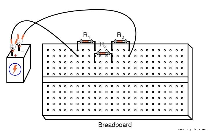
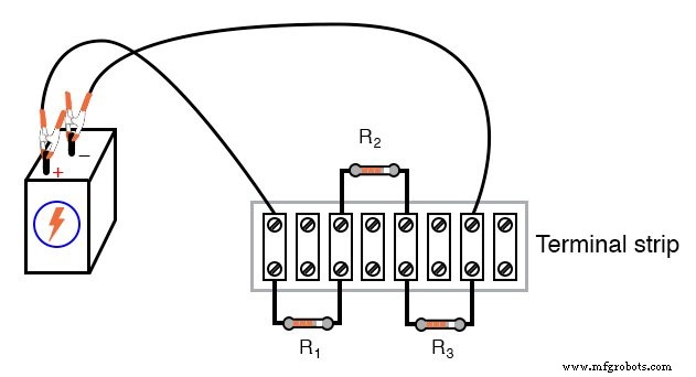
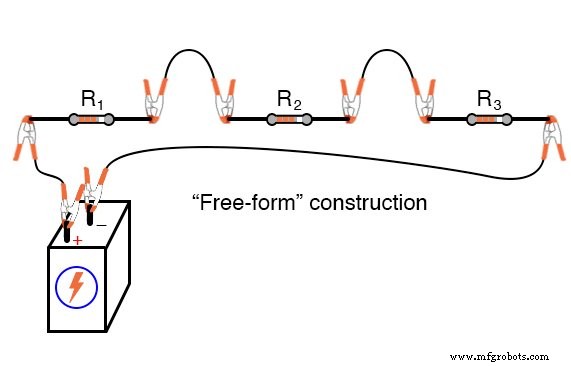
This exercise demonstrates three common construction methods: breadboard, terminal strip, and free‑form. Building the same circuit with each technique will help you appreciate their respective advantages and limitations. The free‑form approach, which uses alligator‑style jumper wires, is suitable for a simple demonstration; breadboards provide versatility and high component density but are temporary; terminal strips offer a more permanent assembly at the expense of space.
Select three resistors from your assortment and verify each value with an ohmmeter. Record the measurements. Connect the resistors in series and attach them to the 6‑volt battery as shown. Measure the battery voltage with a voltmeter while the circuit is powered, and note this reading. Although the load is light, measuring under load yields data that reflects real operating conditions.
Use Ohm’s Law (I = E/R) to calculate the expected circuit current. Verify this value by measuring the current with an ammeter (see the terminal‑strip example below).
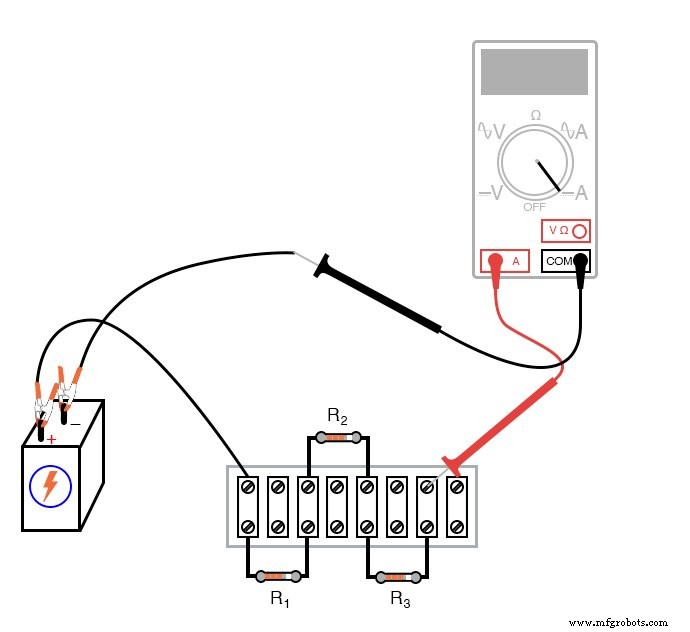
With resistor values between 1 kΩ and 100 kΩ and a 6‑volt source, the current will be in the milliampere or microampere range. Digital meters typically indicate the scale (m or μ) on the display; be sure to read it correctly.
Next, use the calculated current to predict the voltage drop across each resistor (V = I R). Switch your multimeter to voltage mode and measure each drop. The measured values should match the predictions closely, confirming the voltage‑divider principle: each resistor’s drop is a fixed fraction of the total voltage, determined by its resistance relative to the series total.
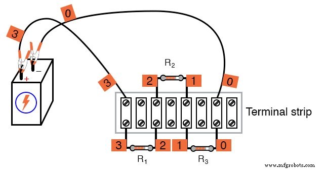
The following section validates Kirchhoff’s Voltage Law (KVL). Assign a unique number to each distinct node in the circuit; nodes that are directly connected share the same number. For example, use numbers 0–3 as illustrated below. Attach small labels or tape to indicate the node numbers on the actual circuit.
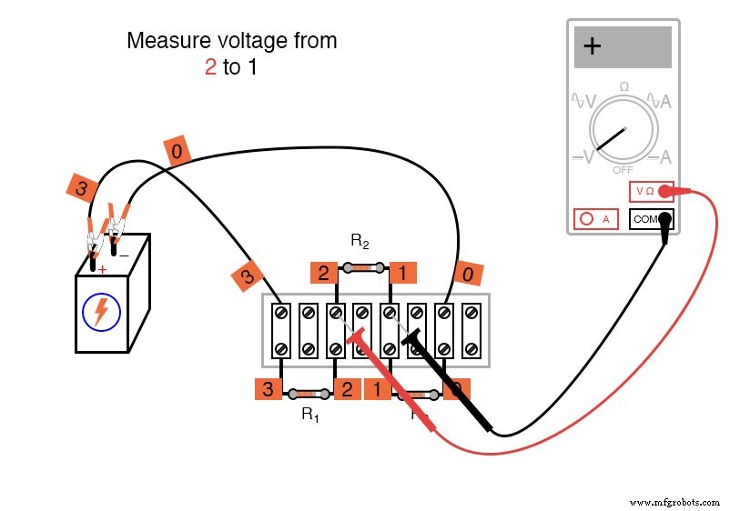
Using a digital voltmeter, measure the voltage difference around a closed loop (e.g., 0 → 1 → 2 → 3 → 0). Record each reading with its sign as displayed—do not reverse probe connections to force a “positive” result. Sum the signed voltages algebraically; the total should be zero, demonstrating KVL. You may choose any loop that starts and ends at the same node; all such loops will satisfy the law.
Below are illustrative steps around the 0‑1‑2‑3‑0 loop:
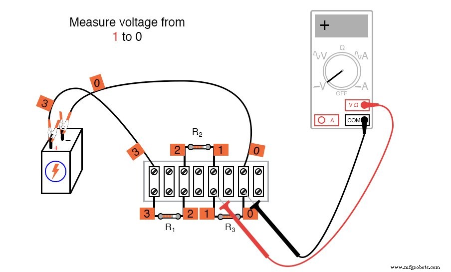
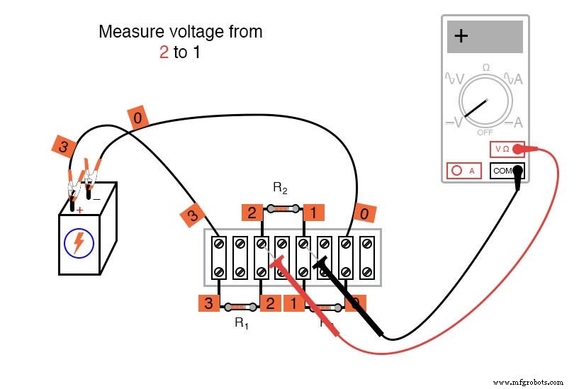
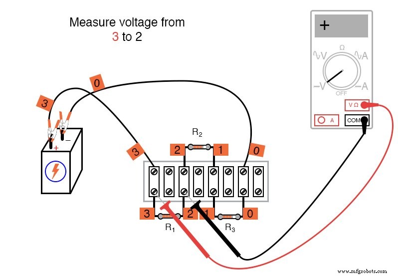
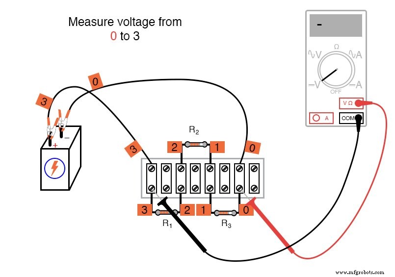
Typical measurements yield three positive values and one negative; algebraically adding them should produce zero.
Feel free to experiment with different loops, such as 1 → 2 → 3 → 1, and verify that the algebraic sum remains zero. This property holds regardless of circuit topology.
Kirchhoff’s Voltage Law is a powerful analytical tool that enables prediction of voltage magnitudes and polarities in any network by ensuring that the algebraic sum around any closed path is zero.
COMPUTER SIMULATION
Netlist (create a text file containing the following verbatim):
Voltage divider
v1 3 0
r1 3 2 5k
r2 2 1 3k
r3 1 0 2k
.dc v1 6 6 1 * Voltages around 0-1-2-3-0 loop algebraically add to zero
.print dc v(1,0) v(2,1) v(3,2) v(0,3) * Voltages around 1-2-3-1 loop algebraically add to zero
.print dc v(2,1) v(3,2) v(1,3)
.end
The simulation uses nodes 0–3, with resistor values chosen to provide 50%, 30%, and 20% of the total voltage across R1, R2, and R3, respectively. You may alter the source voltage or resistor values as desired. Running the simulation will output voltage values; summing each line confirms the law.
RELATED WORKSHEETS:
Voltage Divider Circuits Worksheet
Industrial Technology
- Exploring Voltage Addition with Series Battery Connections
- Voltage Divider Lab: Design, Measurement, and Kirchhoff’s Voltage Law Verification
- Hands‑On Guide to Current Dividers: Build, Measure, and Simulate with a 6 V Battery
- Building a Precise Voltage Divider with a Potentiometer
- Thermoelectricity: Understanding Thermocouples and the Seebeck Effect
- Build a Potato Battery: A Step‑by‑Step Guide to DIY Electrochemical Power
- Voltage Divider Circuits: Mastering Series Resistor Analysis & Potentiometers
- Tachogenerators: Precision Speed Measurement for Industrial Motors and Equipment
- Understanding AC Waveforms: Sine Waves, Frequency, and Oscilloscope Basics
- Mastering Capacitive Voltage Dividers: Design, Theory, and Practical Applications