


Understanding Voltage Drop Polarity in Circuit Analysis
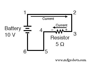
In a typical DC circuit powered by a single battery, conventional current flows from the positive (+) terminal toward the negative (–) terminal. In the example below, the current circulates clockwise through points 1 → 2 → 3 → 4 → 5 → 6 and back to 1.
When the current passes through the 5 Ω resistor, a voltage drop occurs across its terminals. By definition, the end where the current enters is marked positive, and the exit end is marked negative. Thus, the resistor’s voltage drop is +10 V at point 3 relative to point 4.
We can annotate the polarity of each voltage drop in the circuit with a simple rule: positive sign at the current‑entry end, negative sign at the exit end.
Below is a comprehensive table that lists the voltage polarity between every pair of reference points in this circuit:
Between points 1 (+) and 4 (–) = 10 V
Between points 2 (+) and 4 (–) = 10 V
Between points 3 (+) and 4 (–) = 10 V
Between points 1 (+) and 5 (–) = 10 V
Between points 2 (+) and 5 (–) = 10 V
Between points 3 (+) and 5 (–) = 10 V
Between points 1 (+) and 6 (–) = 10 V
Between points 2 (+) and 6 (–) = 10 V
Between points 3 (+) and 6 (–) = 10 V
While it may seem trivial to record polarity in a simple loop, mastering this concept is essential for analyzing more intricate networks that contain multiple resistors, voltage sources, or both.
Polarity is Independent of Ohm’s Law
Polarity does not enter Ohm’s Law calculations—there are never negative values for V, I, or R in Ohm’s Law itself. However, other electrical equations (e.g., Kirchhoff’s Voltage Law) explicitly account for sign convention when summing voltages around a loop.
Key Take‑away
- The polarity of a voltage drop across a resistive element follows the current direction: + at the entry, – at the exit.
Related Worksheets
Industrial Technology
- Exploring Voltage Addition with Series Battery Connections
- Voltage Divider Lab: Design, Measurement, and Kirchhoff’s Voltage Law Verification
- Thermoelectricity: Understanding Thermocouples and the Seebeck Effect
- Potentiometric Voltmeter: Precise Voltage Measurement with Minimal Loading
- Build a Potato Battery: A Step‑by‑Step Guide to DIY Electrochemical Power
- Low‑Voltage AC Power Supply: Phase‑Shift Circuit Components & Best Practices
- Voltage Regulator Experiment with a 12‑Volt Zener Diode
- Tachogenerators: Precision Speed Measurement for Industrial Motors and Equipment
- Understanding AC Waveforms: Sine Waves, Frequency, and Oscilloscope Basics
- Understanding Polarity and Phase in AC Circuit Analysis