


Wire Resistance in Circuits: Why Length & Shape Usually Don’t Matter
Up to now, we’ve examined simple single‑battery, single‑resistor circuits without considering the connecting wires. But does the wire’s length or the circuit’s shape influence our calculations? The following diagrams clarify the answer.
In most textbook analyses, the wires are treated as having zero resistance. Consequently, only the components’ resistances—here, the two 5 Ω resistors—contribute to the total resistance of the loop. In reality, metal conductors do have resistance, but it is usually so small relative to component values that it can be ignored for low‑power, low‑current circuits. Exceptions arise in high‑current power‑distribution systems, where even a few milliohms per meter can produce significant voltage drops.
Electrically Common Points in a Circuit
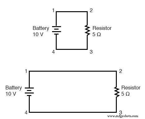
When wire resistance is negligible, any two points joined by a wire are electrically common. Whether points 1 and 2 are physically close or far apart, the voltage measured between them is effectively the same, and the same applies to points 3 and 4. This property allows you to redraw or rewire a circuit—shortening or lengthening wires—without affecting its electrical behavior, provided the component sequence remains unchanged.
It also means that voltage readings taken between electrically common points are identical. For instance, the voltage across the battery (points 1 to 4) equals the voltage across the resistor (points 2 to 3). The following example illustrates this principle.
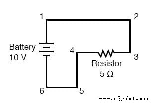
In that circuit, the only active elements are a battery and a resistor, yet the wires form a winding path. Points 1, 2, and 3 are all electrically common, as are points 4, 5, and 6. The battery supplies 10 V, so the voltage between points 1 and 6 is 10 V. Because points 5 and 4 are common to 6, and points 2 and 3 are common to 1, the same 10 V appears across all other pairings:
Between points 1 and 4 = 10 V
Between points 2 and 4 = 10 V
Between points 3 and 4 = 10 V (directly across the resistor)
Between points 1 and 5 = 10 V
Between points 2 and 5 = 10 V
Between points 3 and 5 = 10 V
Between points 1 and 6 = 10 V (directly across the battery)
Between points 2 and 6 = 10 V
Between points 3 and 6 = 10 V
Conversely, because the wires have no resistance, the voltage between any two common points is effectively zero:
Between points 1 and 2 = 0 V
Between points 2 and 3 = 0 V
Between points 1 and 3 = 0 V
Between points 4 and 5 = 0 V
Between points 5 and 6 = 0 V
Between points 4 and 6 = 0 V
Calculating the Voltage Drop with Ohm’s Law
With a 10 V battery and a 5 Ω resistor, the loop current is 2 A. Assuming zero wire resistance, Ohm’s Law gives the voltage drop across any uninterrupted length of wire as V = IR = I × 0 = 0 V, regardless of the current magnitude.
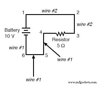
Because common points share the same voltage, wires that connect them are often given identical designations. For example, in the diagram below, the wire linking point 1 to 2 is labeled “wire 2,” just like the wire from point 2 to 3. In practice, the physical characteristics of these wires may differ, but their symbolic labels reflect the common electrical potential.
Voltage Drop Should Equal Zero in Common Points
Recognizing that voltage between electrically common points is zero is a powerful troubleshooting cue. If a voltage measurement between two supposed common points yields a non‑zero reading, you can immediately suspect an open connection or a fault in the wiring.
Zero Voltage is an Idealization
In practice, all conductors have some finite resistance, except for superconductors. Therefore, the “zero‑voltage” rule applies strictly under ideal conditions. Real wires will exhibit a very small, yet measurable, voltage drop proportional to the current and their resistance. Nevertheless, for most low‑power circuits, the resulting deviation is negligible and the ideal assumptions remain valid.
Review:
- Unless specified otherwise, wires in circuit analysis are treated as having zero resistance.
- Wires can be shortened or lengthened without affecting circuit performance, as long as the component sequence is preserved.
- Points directly connected by zero‑resistance wire are considered electrically common.
- Voltage between electrically common points is zero (ideally) regardless of current.
- Voltage or resistance measurements between sets of common points are identical.
- These rules hold under ideal assumptions; in real life, minimal wire resistance introduces only trace voltage drops.
Related Worksheets:
- Simple Circuits Worksheet
- Elementary Circuit Worksheet
- Voltage Divider Circuit Worksheet
Industrial Technology
- Mastering AC Circuit Equations: Impedance, Reactance & Resonance
- Voltage and Current in a Practical Circuit: Understanding Their Relationship
- How Test Points Enhance PCB Testing and Production Efficiency
- Step‑by‑Step Guide: Wiring GFCI Circuit Breakers for 1‑ to 4‑Pole Systems
- Installing a GFCI Outlet: Step‑by‑Step Wiring Guide & Circuit Diagrams
- Corridor Wiring Diagram: Mastering 2‑Way Switch Control for Hallway Lighting
- Switch‑Based Lighting System for Hospital Patient Rooms
- Hotel Bell Indicator Circuit – Comprehensive Hotelling Wiring Guide
- Key Considerations for High-Quality PCB Manufacturing
- Potentiometer Wiring Made Easy: A Professional Guide