


Nonlinear Conduction: How Resistance Changes Shape Real-World Circuits
“Advances are made by answering questions. Discoveries are made by questioning answers.”
—Bernhard Haisch, Astrophysicist
Ohm’s Law remains a cornerstone of electrical engineering, yet its simplicity masks a crucial limitation: it assumes a constant resistance. In practice, many conductors, especially those exposed to heat or high fields, exhibit resistance that varies with temperature, voltage, or current.
When Resistance Is Constant
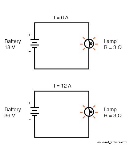
For most metallic wires used in low‑power circuits, the resistance change is negligible. A 3 Ω lamp powered by an 18‑V battery carries 6 A (I = E/R). Doubling the supply to 36 V doubles the current to 12 A, confirming the linear I–V relationship when the lamp’s filament resistance remains stable.
Temperature‑Dependent Resistance in Incandescent Lamps
In an incandescent lamp, the tungsten filament’s resistance rises sharply as it heats from room temperature to its operating temperature (~2500 K). The higher current raises the filament temperature, which in turn increases resistance, limiting further current increase without raising the supply voltage.
Because the filament’s resistance is not constant, the simple formula I = E/R no longer holds across all operating points.
Visualizing Linear vs. Nonlinear I–V Curves
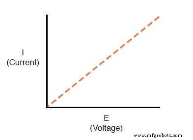
With a constant resistance, the I–V plot is a straight line:
A realistic lamp circuit, however, yields a curved plot that starts steep and flattens as voltage increases:
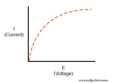
Here, resistance increases with current and voltage, illustrating nonlinearity caused by thermal effects.
Nonlinear Conduction in Gases
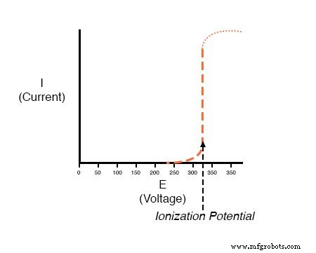
Air is an excellent insulator at standard conditions. When the voltage across an air gap exceeds its ionization potential, the gas becomes conductive, allowing a sudden surge of current. This behavior underpins lightning strikes and spark gaps.
For a small gap (<1 in), the I–V curve shows negligible current until the breakdown voltage, after which current rises sharply:
In solids, a similar high‑field breakdown can permanently lower the breakdown voltage, compromising insulation integrity.
Engineered Nonlinear Components
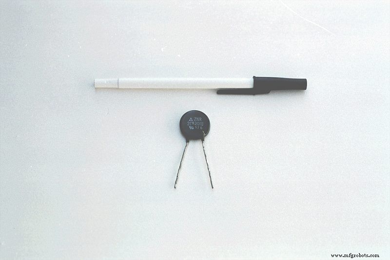
Varistors are designed to exhibit high resistance until a specified “firing” voltage, beyond which resistance drops dramatically. They protect circuits from voltage spikes.
Gas‑filled tubes, such as neon or mercury lamps, also rely on ionization to conduct.
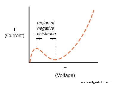
Some devices display negative resistance, where increasing voltage reduces current. Examples include tetrode vacuum tubes and Esaki (tunnel) diodes, which are essential in oscillators and amplifiers.
Key Takeaways
- Most conductors maintain stable resistance over typical operating ranges, but not all.
- Linear I–V plots (straight lines) indicate constant resistance; nonlinear plots reveal resistance that varies with voltage or current.
- Varistors protect against overvoltage by sharply reducing resistance at a preset threshold.
- Negative resistance occurs when current decreases as voltage increases, seen in specialized tubes and diodes.
Further Learning
Industrial Technology
- Practical Ohm’s Law Experiment: Measuring Voltage, Current, and Resistance
- Exploring Nonlinear Resistance in Incandescent Lamps: A Practical Lab Guide
- Exploring Voltage Addition with Series Battery Connections
- Ohm’s Law Explained: How Voltage, Current, and Resistance Interact in Electrical Circuits
- Resistors: Fundamentals, Types, and Practical Applications
- Understanding Conductance: The Inverse of Resistance
- High‑Voltage Ohmmeter Design and Application
- Tachogenerators: Precision Speed Measurement for Industrial Motors and Equipment
- Calculating Wire Resistance for Voltage‑Drop‑Critical Circuits
- Understanding AC Waveforms: Sine Waves, Frequency, and Oscilloscope Basics