


Exploring Nonlinear Resistance in Incandescent Lamps: A Practical Lab Guide
PARTS AND MATERIALS
- Calculator (or pencil and paper for arithmetic)
- 6‑volt battery
- Low‑voltage incandescent lamp (Radio Shack catalog #272‑1130 or equivalent)
CROSS‑REFERENCES
Lessons In Electric Circuits, Volume 1, chapter 2: “Ohm’s Law”
LEARNING OBJECTIVES
- Use of voltmeter, ammeter, and ohmmeter
- Apply Ohm’s Law in real circuits
- Recognize that some resistances vary with operating conditions
- Employ the scientific method to test hypotheses
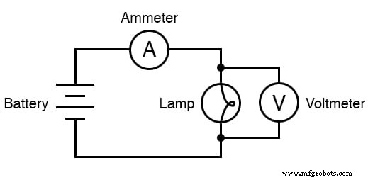
SCHEMATIC DIAGRAM
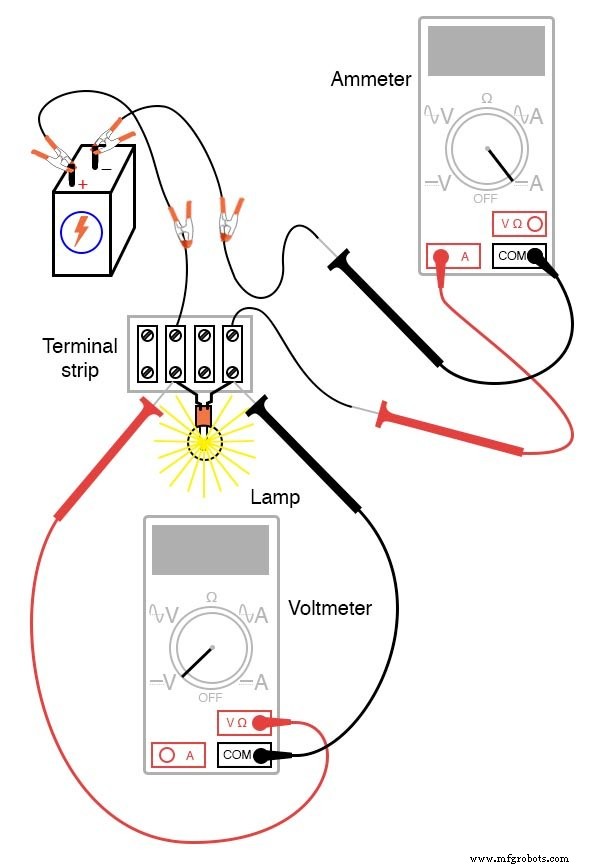
ILLUSTRATION
INSTRUCTIONS
1. Measure the lamp’s resistance with a multimeter while it is **unpowered**. This value reflects the thin metal filament inside the lamp and will be higher than a jumper wire but lower than the resistors used in previous experiments. Record this figure for later comparison.
2. Construct a simple one‑battery, one‑lamp series circuit. Set the multimeter to the appropriate voltage range and record the voltage across the lamp once it lights. Keep this value alongside the resistance you measured earlier.
3. Switch the multimeter to its highest current range (or let it auto‑range) and insert the ammeter in series with the battery and lamp. Choose a range that gives a clear reading without over‑ranging. Record the measured current along with the previously noted voltage and resistance.
4. Calculate the expected current using Ohm’s Law: I = V ÷ R. Compare this calculated current to the one you measured. Typically, the calculated current will be significantly higher than the measured value.
5. Re‑measure the lamp’s resistance using a different model of meter (analog vs. digital). Remember that resistance should only be measured on an unpowered component; otherwise, external voltages will skew the reading. Analog meters often report a higher resistance for the same lamp than digital meters.
6. Reflect on why the lamp’s resistance changes between lit and unlit states or when measured with different meters. Consider factors such as filament temperature, material properties, and the meter’s internal resistance. Formulate a hypothesis explaining this nonlinear behavior.
7. Test your hypothesis by introducing an external variable—such as additional light exposure—to the lamp while measuring its resistance. If the resistance changes in response, your hypothesis gains evidence; if not, it is falsified and you must seek an alternative explanation.
By following this systematic approach, you will gain hands‑on experience with measurement techniques, deepen your understanding of nonlinear resistance, and practice the scientific method in a controlled laboratory setting.
Industrial Technology
- Understanding Electrical Resistance and Circuit Safety
- Resistors: Fundamentals, Types, and Practical Applications
- Nonlinear Conduction: How Resistance Changes Shape Real-World Circuits
- Understanding Conductance: The Inverse of Resistance
- Bridge Circuits: Wheatstone, Kelvin, and Their Role in Precise Electrical Measurements
- Battery Construction Fundamentals: Cells, Internal Resistance, and Connectivity
- Calculating Wire Resistance for Voltage‑Drop‑Critical Circuits
- Temperature Coefficient of Resistance: How Temperature Alters Conductivity
- Lava Lamp: History, Design, and Manufacturing Secrets
- Enhancing Product Durability: Mastering Polyurethane Impact Resistance