


Practical Ohm’s Law Experiment: Measuring Voltage, Current, and Resistance
Materials Needed
- Scientific calculator or a pencil and paper for arithmetic calculations
- 6‑volt battery (fresh and fully charged)
- Resistors ranging from 1 kΩ to 100 kΩ (preferably precision metal‑film types)
We recommend staying within the 1 kΩ–100 kΩ range. At lower values the ammeter’s internal resistance skews the reading, while at very high values the voltmeter’s parallel resistance can alter the circuit’s effective resistance. Within this band, meter impact is minimal, ensuring that calculated and measured values agree within a few percent.
Cross‑References
Lessons In Electric Circuits, Volume 1, Chapter 2: “Ohm’s Law” – a foundational text for this experiment.
Learning Objectives
- Accurate use of a voltmeter, ammeter, and ohmmeter
- Application of Ohm’s Law to real circuits
- Interpretation of measurement error and its sources
Schematic Diagram
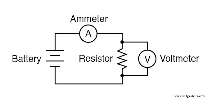
Illustration
Step‑by‑Step Instructions
- Select a resistor from the assortment and measure its resistance with a multimeter set to the correct range. Avoid touching the terminals during measurement to prevent body resistance from affecting the result.
- Record the measured resistance for later use.
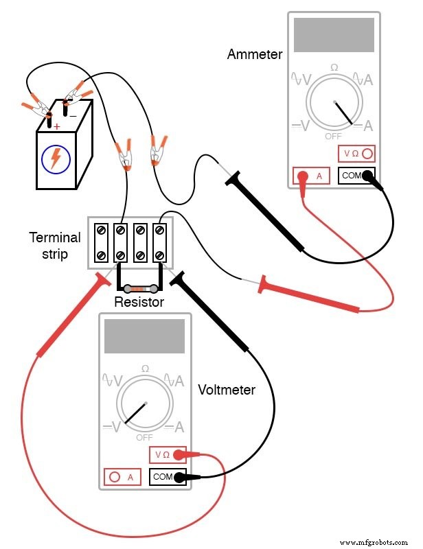
- Build a single‑battery, single‑resistor circuit (a terminal strip works well, but any breadboard or simple wire setup is acceptable).
- Set the multimeter to the appropriate voltage range and measure the voltage drop across the resistor while the circuit is powered. Record this voltage.
- Switch the multimeter to the highest current range, then break the circuit and insert the ammeter in series with the battery and resistor. Choose the range that provides the strongest reading without over‑ranging.
- Record the current reading, along with the previously noted resistance and voltage.
- Using the measured voltage and resistance, calculate the current with Ohm’s Law (I = V/R). Compare this calculated current to the measured value.
- Repeat the calculation in reverse: use the measured voltage and current to compute resistance (R = V/I) and compare with the measured resistance.
- Finally, compute the voltage from the measured resistance and current (V = I × R) and verify it against the measured voltage.
- All measured and calculated values should agree within a few percent; any larger discrepancy likely points to meter inaccuracies.
- Repeat the entire process with different resistors to observe how changes in resistance affect current while the supply voltage remains constant.
For a quick reference, try our Ohm’s Law Calculator to verify your results on the fly.
Related Worksheets
- Basic Voltmeter Use Worksheet
- Basic Ohmmeter Use Worksheet
- Basic Ammeter Use Worksheet
- Simple Circuits Worksheet
These worksheets reinforce the concepts and provide additional practice with real data.
Industrial Technology
- Ohm’s Law Explained: How Voltage, Current, and Resistance Interact in Electrical Circuits
- Ohm’s Law Explained: A Water‑Pipe Analogy for Clear Intuition
- Resistors: Fundamentals, Types, and Practical Applications
- Nonlinear Conduction: How Resistance Changes Shape Real-World Circuits
- Understanding Ohm’s Law and the Real Risks of Electrical Shock
- Understanding Conductance: The Inverse of Resistance
- Mastering Ohm’s Law: Correct Application and the Table Method for Accurate Circuit Analysis
- Kirchhoff’s Voltage Law (KVL): A Practical Guide to Voltage Circuits
- High‑Voltage Ohmmeter Design and Application
- Tachogenerators: Precision Speed Measurement for Industrial Motors and Equipment