


Mastering Ohm’s Law: Correct Application and the Table Method for Accurate Circuit Analysis
Reminders When Using Ohm’s Law
One of the most frequent pitfalls for beginner electronics students is confusing the contexts of voltage, current, and resistance. A common error is using the current that flows through one resistor together with the voltage measured across a set of interconnected resistors, assuming the result will give the resistance of that single resistor. That assumption is incorrect.
Remember: In Ohm’s Law, every variable must refer to the same two terminals in the circuit under analysis. This rule is crucial, especially in series‑parallel networks where adjacent components can exhibit distinct voltage drops and currents.
When calculating a parameter for a single component, ensure that the voltage you use is the drop across that component alone, the current is the current that flows solely through it, and the resistance is the intrinsic resistance of that component. Similarly, for a group of components, all three quantities must pertain to the entire group between its two defining points.
A practical way to keep these relationships clear is to focus on the two points that terminate the component or group being analyzed. Verify that the voltage is measured across those points, the current represents the flow from one point to the other, the resistance is the equivalent resistance between them, and the power is the total dissipation in every element between those points.
Notes on the “Table” Method of Analyzing Circuits
The table method illustrated for both series and parallel circuits in this chapter offers a structured approach that keeps Ohm’s Law variables correctly contextualized for any configuration. In a table like the one below, you should apply Ohm’s Law only to the values within a single vertical column at a time:
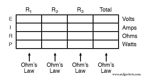
Horizontal derivations across columns are valid when applying the principles of series and parallel connections:
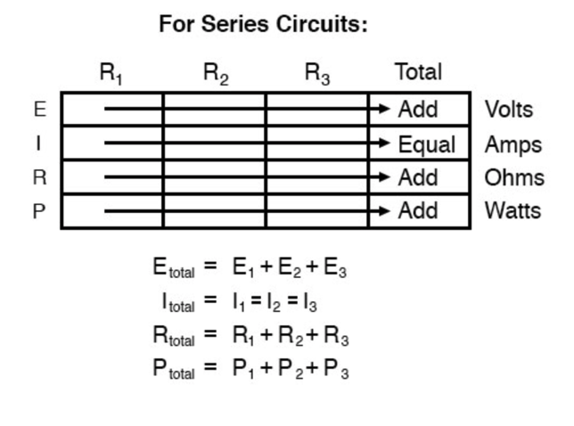
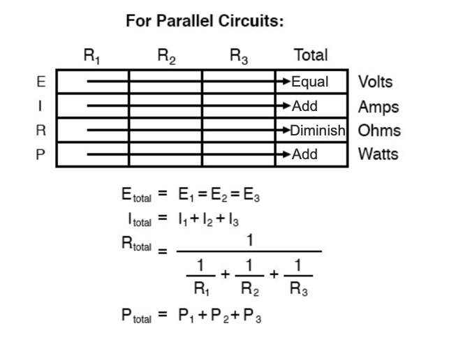
Beyond simplifying data management, the table method facilitates cross‑checking. After solving for all unknown voltages, currents, and resistances, add a bottom row to calculate power per resistor and confirm that the sum equals the total circuit power. A mismatch signals an error in earlier steps.
While cross‑checking is a standard practice, arranging all values in a table minimizes confusion and enhances accuracy.
REVIEW:
- Apply Ohm’s Law to each vertical column in the table.
- Use series/parallel rules for horizontal rows.
- Validate results by working backward to recover given values or by solving a quantity through multiple methods.
Try out our Ohm’s Law Calculator in our Tools section.
RELATED WORKSHEETS:
- Ohm’s Law Practice Worksheet With Answers Worksheet
- Series DC Circuits Practice Worksheet with Answers Worksheet
- Parallel DC Circuits Practice Worksheet With Answers Worksheet
- Series-Parallel DC Circuits Worksheet
- Basic Algebra and Graphing for Electric Circuits Worksheet
Industrial Technology
- Practical Ohm’s Law Experiment: Measuring Voltage, Current, and Resistance
- Ohm’s Law Explained: How Voltage, Current, and Resistance Interact in Electrical Circuits
- Ohm’s Law Explained: A Water‑Pipe Analogy for Clear Intuition
- Understanding Ohm’s Law and the Real Risks of Electrical Shock
- Kirchhoff’s Voltage Law (KVL): A Practical Guide to Voltage Circuits
- Quantum Computer Achieves Time-Reversal, Challenging Thermodynamics
- Choosing the Right Bit for Plunge Routing: A Practical Guide
- 5 Key Benefits of Partnering with a Professional 3D Printing Service
- Choosing Urethane Casting: Ideal Applications & Benefits
- How to Correctly Use, Repair, and Maintain Precision Measuring Tools