


Kirchhoff’s Voltage Law (KVL): A Practical Guide to Voltage Circuits
What Is Kirchhoff’s Voltage Law (KVL)?
Kirchhoff’s Voltage Law, formulated by German physicist Gustav R. Kirchhoff in 1847, states:
"The algebraic sum of all voltages in any closed loop must equal zero."
The term “algebraic” means that both the magnitude and the polarity of each voltage must be considered. A “loop” refers to any path that starts at a point in a circuit, follows connected elements, and returns to the starting point.
Demonstrating KVL in a Series Circuit
Consider the series circuit below. Points are numbered for reference:
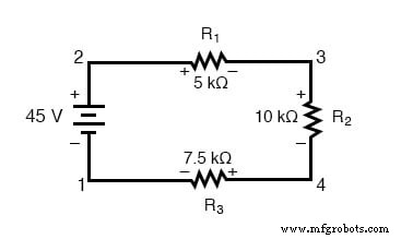
Measuring the voltage between points 2 and 1 with a voltmeter (red lead on 2, black on 1) yields +45 V. The double subscript notation E2-1 indicates the potential at point 2 relative to point 1.
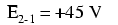
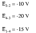
Stepping around the loop clockwise and recording the voltage across each resistor gives the following readings:
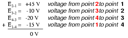
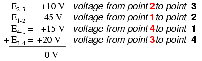
When the polarity of each measurement is respected, the algebraic sum of the voltages in the loop is zero:
Changing the starting point or the direction of traversal (e.g., 3‑2‑1‑4‑3) yields the same result:
Re‑drawing the circuit in a straight line clarifies the polarity relationship:
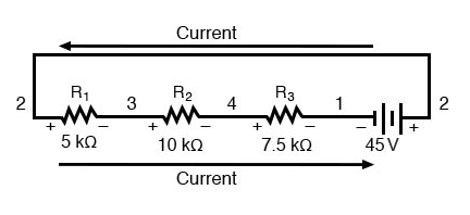
In this layout, the battery’s voltage is negative on the left and positive on the right, while each resistor’s voltage drop is oriented oppositely. The opposing polarities reflect the fact that resistors oppose the current supplied by the battery.
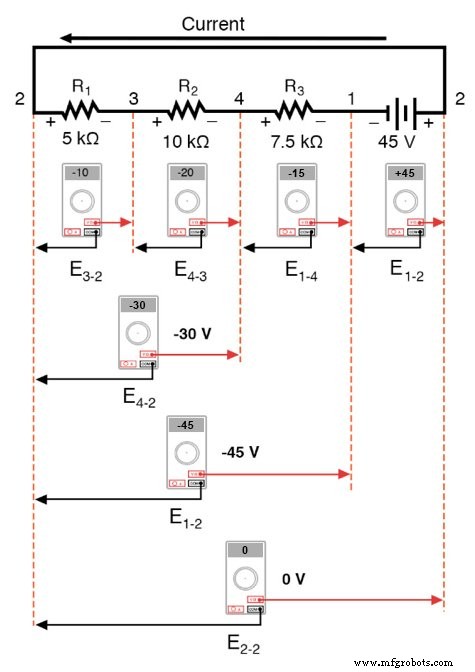
Voltages measured across the components, with the black lead on the left and the red lead on the right, are:
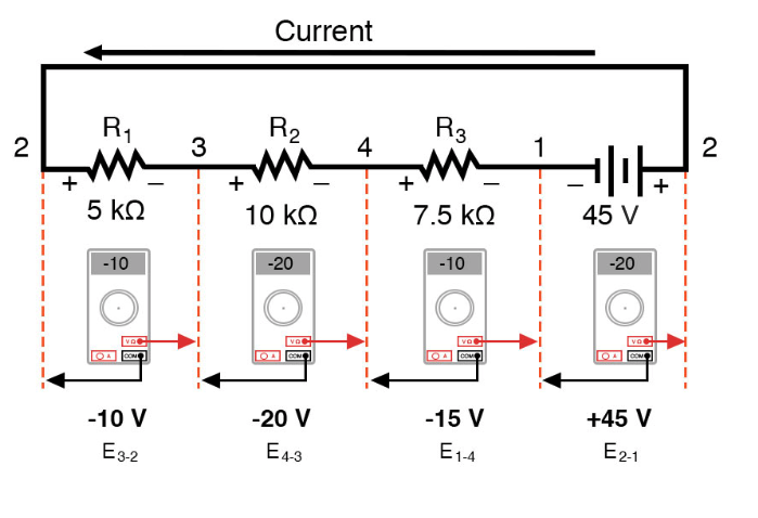
Summing the voltages algebraically across the entire series string confirms that the total equals zero, as the far‑left and far‑right terminals are electrically common.
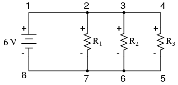
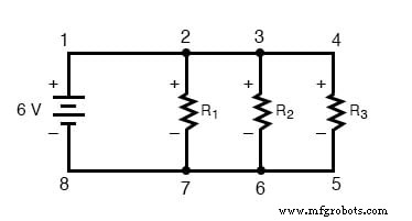
Demonstrating KVL in a Parallel Circuit
Kirchhoff’s Law applies to any topology, including parallel networks. In the circuit below, each resistor experiences the same 6 V supply:
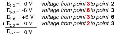
Traversing loop 2‑3‑4‑5‑6‑7‑2 yields a zero algebraic sum:
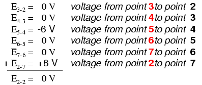
Note that the final term is labeled E2-2, representing the voltage measured between the same starting and ending point, which must be zero.
Validity of KVL in Any Circuit
The law remains valid regardless of whether the circuit is series, parallel, or a “black box” with hidden internal components. The loop for KVL can even include non‑physical paths, as long as the start and end points coincide:
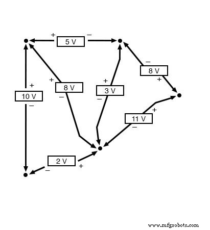
Any traversal around such a loop will always produce a zero algebraic sum. For example, the non‑conventional loop 2‑3‑6‑3‑2 in the parallel circuit still sums to zero:
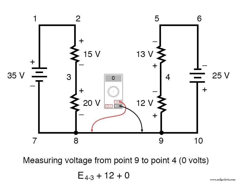
Using KVL in a Complex Circuit
Consider the following circuit, which consists of two series branches joined by a common wire:
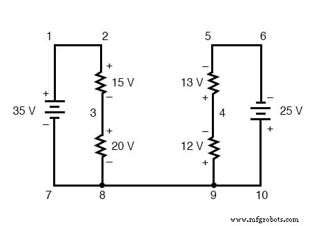
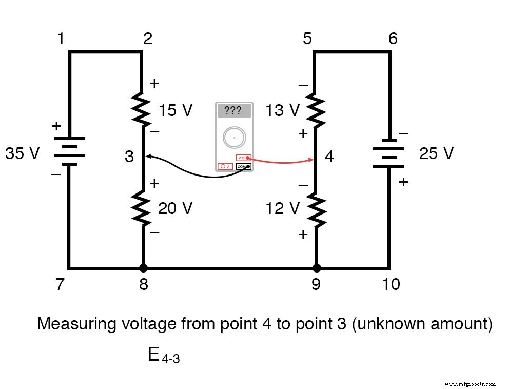
To find the unknown voltage between points 4 and 3, set up a KVL equation around loop 3‑4‑9‑8‑3:
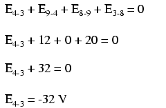
Using the same lead orientation as a digital voltmeter (red lead on the forward point, black on the backward), the voltages are:
Solving yields E4-3 = -32 V, indicating that point 3 is 32 V higher than point 4. Reversing the lead orientation would give E3-4 = +32 V, the same physical result expressed differently.
Review
- Kirchhoff’s Voltage Law (KVL): "The algebraic sum of all voltages in a loop must equal zero."
Related Worksheets
- Kirchhoff’s Laws Worksheet
Industrial Technology
- Practical Ohm’s Law Experiment: Measuring Voltage, Current, and Resistance
- Exploring Voltage Addition with Series Battery Connections
- Voltage Divider Lab: Design, Measurement, and Kirchhoff’s Voltage Law Verification
- Thermoelectricity: Understanding Thermocouples and the Seebeck Effect
- Ohm’s Law Explained: How Voltage, Current, and Resistance Interact in Electrical Circuits
- Kirchhoff’s Voltage Law (KVL): A Practical Guide to Voltage Circuits
- Kirchhoff’s Current Law (KCL): Fundamentals and Practical Application
- Tachogenerators: Precision Speed Measurement for Industrial Motors and Equipment
- Understanding AC Waveforms: Sine Waves, Frequency, and Oscilloscope Basics
- Kirchhoff’s Laws: Current & Voltage (KCL & KVL) – Step‑by‑Step Solved Example