


Exploring Voltage Addition with Series Battery Connections
PARTS AND MATERIALS
- Two 6‑V batteries
- One 9‑V battery
Any battery sizes will work, but using two different voltages makes the experiment more illustrative.
CROSS‑REFERENCES
Lessons In Electric Circuits, Volume 1, chapter 5: “Series and Parallel Circuits”
Lessons In Electric Circuits, Volume 1, chapter 11: “Batteries and Power Systems”
LEARNING OBJECTIVES
- Demonstrate how connecting batteries in series increases total voltage.
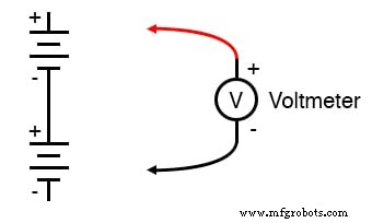
SCHEMATIC DIAGRAM
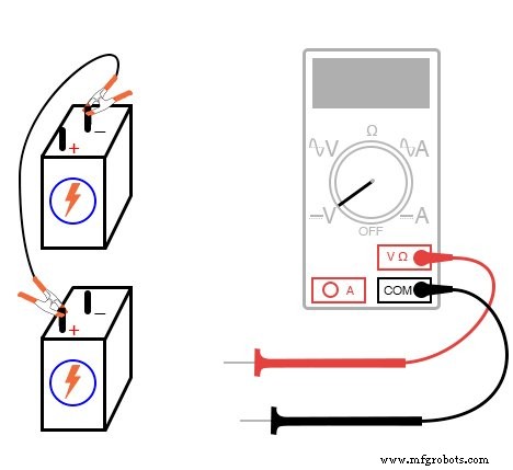
ILLUSTRATION
INSTRUCTIONS
Connecting components in series means linking them end‑to‑end so that there is a single path for electrons to flow through all devices. When batteries are connected with the positive terminal of one to the negative terminal of the next, their voltages simply add.
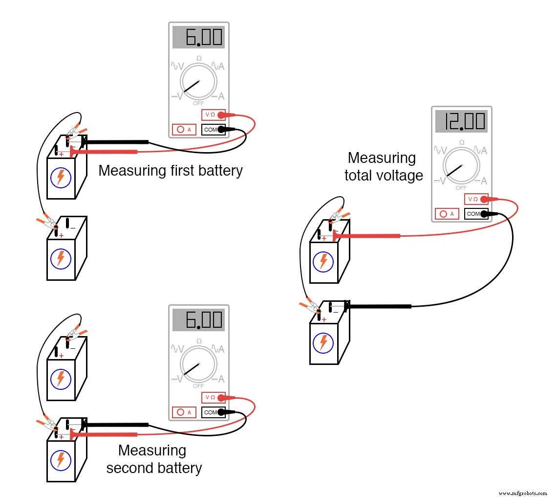
Measure the voltage of each battery separately as you connect them, then measure the combined voltage across the pair, as illustrated below:
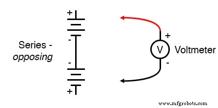
Try connecting batteries of different ratings in series—for example, a 6‑V battery with a 9‑V battery. What will the total voltage be? Then reverse the polarity of one battery so that the terminals oppose each other, and observe how the total voltage changes:
Notice the polarity indicated by your voltmeter: a positive reading means the red probe is on the positive side, while a negative reading indicates reversed polarity (red probe on the negative side). Analog meters will not display correctly if the connections are reversed because the needle moves in the wrong direction.
Can you predict the overall voltage polarity based on the individual battery polarities and strengths?
RELATED WORKSHEETS:
- Batteries Worksheet
Industrial Technology
- Voltage Divider Lab: Design, Measurement, and Kirchhoff’s Voltage Law Verification
- Thermoelectricity: Understanding Thermocouples and the Seebeck Effect
- Potentiometric Voltmeter: Precise Voltage Measurement with Minimal Loading
- Tachogenerators: Precision Speed Measurement for Industrial Motors and Equipment
- Understanding AC Waveforms: Sine Waves, Frequency, and Oscilloscope Basics
- Analyzing Series Resistor‑Inductor AC Circuits: Impedance, Phase, and SPICE Verification
- Series A vs Series B Flanges: Key Differences & Applications
- Choosing the Right Battery Connection: Series, Parallel, and Series‑Parallel Configurations
- Connecting Batteries in Series-Parallel to a Solar Panel: A Step‑by‑Step Guide
- Step-by-Step Guide: Wiring Batteries in Series for Solar Panels and UPS Systems