


Superposition Theorem: A Clear Guide to Circuit Analysis
The Superposition Theorem offers a straightforward method for evaluating linear electrical networks by isolating one source at a time. By treating each power source independently, we can determine voltage and current contributions that are then algebraically combined to reveal the behavior of the complete circuit. This approach eliminates the need for simultaneous equation solving, making it especially useful for educational settings and rapid circuit design checks.
Series/Parallel Analysis
To apply the theorem, first short all independent voltage sources and open all independent current sources, leaving only the source of interest active. The modified network is then reduced using classic series‑parallel rules to find the voltage drop or current for that particular source. Repeat the process for every source in the circuit.
Example: 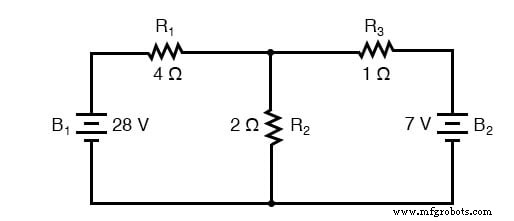
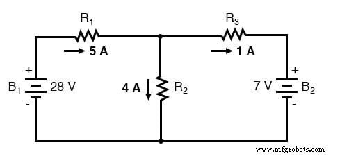
With two batteries (28 V and 7 V), we analyze two separate configurations:
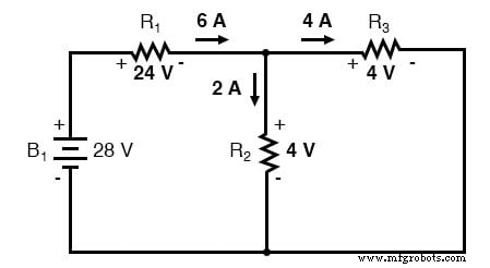
1️⃣ 28‑V source active, 7‑V source shorted: 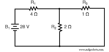
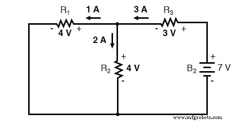
2️⃣ 7‑V source active, 28‑V source shorted: 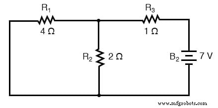
For each case, all inactive voltage sources are replaced by ideal wires (shorts) because a voltage source in zero‑voltage condition behaves like a perfect conductor.
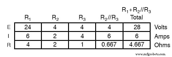
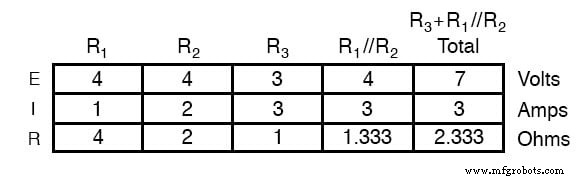
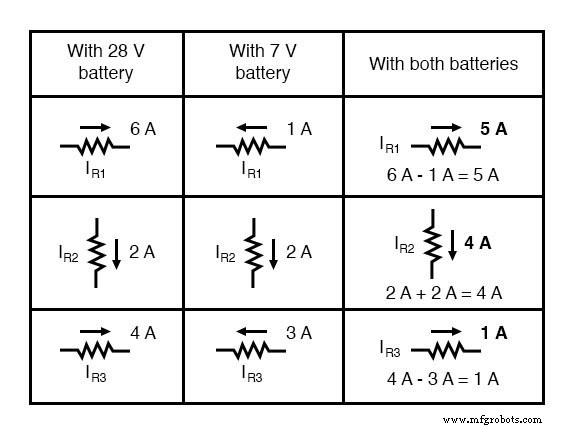
Results for the 28‑V configuration:
Results for the 7‑V configuration:
Superimposing the Results
After computing individual contributions, combine them algebraically, respecting polarity for voltages and direction for currents. The summed voltage across any element is the vector sum of its contributions from each source.
Combined voltage illustration: 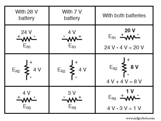
Applying the superimposed voltages to the full circuit yields the final node voltages and branch currents (I = E/R). The same approach can be used directly for currents, as shown below:
Prerequisites and Limitations
- All circuit elements must be linear and bilateral (resistors, ideal sources). Non‑linear devices like incandescent lamps, varistors, or variable resistors invalidate superposition.
- The network must reduce to series/parallel combinations for each isolated source; unbalanced bridge circuits cannot be handled directly.
- Power is a non‑linear function of voltage and current, so superposition cannot be used to compute total power dissipation.
Because AC and DC source equations remain linear, the theorem is widely applied in AC circuit analysis, amplifier design, and mixed‑signal systems.
Review
- Analyze one source at a time, shorting voltage sources and opening current sources.
- Calculate individual voltage drops and currents using series/parallel reduction.
- Algebraically add the contributions, respecting sign and direction, to obtain the final circuit behavior.
Related Worksheet
Industrial Technology
- Exploring Voltage Addition with Series Battery Connections
- Voltage Divider Lab: Design, Measurement, and Kirchhoff’s Voltage Law Verification
- Thermoelectricity: Understanding Thermocouples and the Seebeck Effect
- Potentiometric Voltmeter: Precise Voltage Measurement with Minimal Loading
- Build a Potato Battery: A Step‑by‑Step Guide to DIY Electrochemical Power
- Tachogenerators: Precision Speed Measurement for Industrial Motors and Equipment
- Millman’s Theorem: A Practical Guide to Parallel Branch Analysis
- Understanding AC Waveforms: Sine Waves, Frequency, and Oscilloscope Basics
- Master the Superposition Theorem: Step‑by‑Step Circuit Analysis with Practical Example
- Compensation Theorem in Circuit Analysis: Proof, Explanation, and Practical Examples