


Millman’s Theorem: A Practical Guide to Parallel Branch Analysis
Millman’s Theorem offers a quick way to determine the common voltage across a set of parallel branches, each containing a voltage source and a series resistance. The theorem applies only to circuits that can be redrawn as a parallel network of such branches.
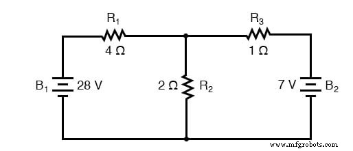
Below we use the same example circuit from previous sections to illustrate the method.
Re‑drawing the circuit for Millman’s Theorem:
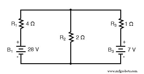
Notice that the battery in the right‑most branch is labeled “B3” to clearly indicate it belongs to the third branch, even though no “B2” is present.
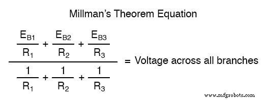
Millman’s Theorem Equation
For a parallel network of branches, the theorem states:
Substituting the actual voltages and resistances from the example gives:
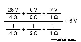
The result, 8 V, is the voltage common to all branches.
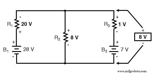
All voltages in the formula are referenced to the same node—here, the bottom wire of the parallel network. In the example, the branch voltages (28 V for branch 1, 0 V for branch 2, 7 V for branch 3) are entered as positive numbers. If the batteries were reversed, the signs would flip, yielding a negative result that indicates the opposite polarity.
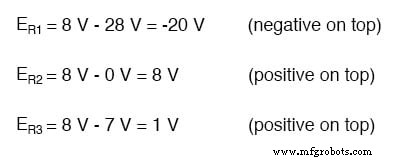
Finding Resistor Voltage Drops
Once the common voltage is known, the voltage drop across each resistor follows from the voltage‑source series relationship:
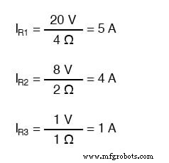
Calculating Branch Currents
Branch currents are then obtained by dividing each resistor’s voltage drop by its resistance:
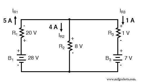
Determining Current Direction
Current direction is dictated by the polarity across each resistor, not the polarity of its battery. A battery can even be reverse‑sunk, as in branch 3. Therefore, pay close attention to the resistor voltage drops when applying Kirchhoff’s Voltage Law to infer current flow.
When to Use Millman’s Theorem
Millman’s Theorem excels in circuits where several voltage sources preclude simple series‑parallel reduction, yet the circuit can be redrawn into parallel branches. It avoids simultaneous equations but is limited to such topologies and does not apply to unbalanced bridge circuits.
Review
- Millman’s Theorem models circuits as parallel branches of series components.
- All voltages are referenced to a common node (typically the bottom of the parallel network).
Related Worksheet
- Millman’s Theorem Worksheet
Industrial Technology
- Exploring Voltage Addition with Series Battery Connections
- Voltage Divider Lab: Design, Measurement, and Kirchhoff’s Voltage Law Verification
- Thermoelectricity: Understanding Thermocouples and the Seebeck Effect
- Tachogenerators: Precision Speed Measurement for Industrial Motors and Equipment
- Superposition Theorem: A Clear Guide to Circuit Analysis
- Millman's Theorem Explained: From Thevenin to Norton and the Millman Equation
- Understanding AC Waveforms: Sine Waves, Frequency, and Oscilloscope Basics
- Millman’s Theorem: Step‑by‑Step AC & DC Circuit Analysis with Practical Examples
- Compensation Theorem in Circuit Analysis: Proof, Explanation, and Practical Examples
- Master the Substitution Theorem: A Step-by-Step Guide with Practical Example