


Understanding Polarity and Phase in AC Circuit Analysis
Complex numbers simplify AC circuit analysis by allowing us to symbolically represent the phase shift between voltage and current. However, many learners find the equivalence between abstract vectors and real circuit quantities challenging. This article clarifies how polarity markings relate to phase angles and why they are essential for accurate analysis.
Voltage is Relative
In both DC and AC circuits, voltage exists only between two points. The choice of test‑lead connections or reference point determines the sign or phase of the measurement. In DC, we use + and – symbols and color‑coded leads (red for +, black for –). In AC, we describe relationships using phase angles rather than signed magnitudes.
For example, a 6‑V source with a + on the left and – on the right is equivalent to a 6‑V source with a – on the left and + on the right, but with its phase shifted by 180°. The polarity marks therefore serve as a reference frame for the phase angle.
Polarity Markings in Battery Symbols
Batteries are traditionally shown with a short line for the negative end and a long line for the positive end. While mathematically a battery could be drawn with reversed polarity and a negative voltage, such notation is unconventional and can be confusing.
Images:
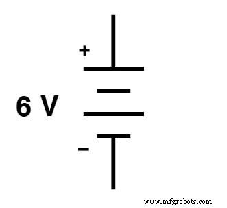
Conventional battery polarity.
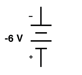
Unconventional polarity marking.
Interpreting a DC Voltmeter Reading
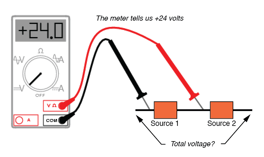
When a digital voltmeter displays a sign, that sign only has meaning once we know which lead is connected to which terminal. For instance, a +24 V reading tells us the black lead is on the negative side and the red lead on the positive side.
Images:
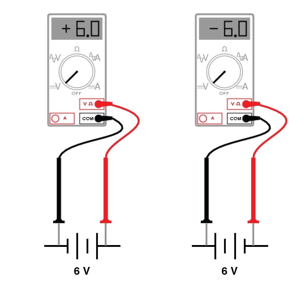
Test lead colors provide a frame of reference for interpreting the sign of the meter’s indication.
Similarly, a –17 V reading indicates that the black lead is actually on the positive side and the red lead on the negative side, implying the battery is oriented opposite to the first one.
Images:
(+) The reading indicates black is (–), red is (+).
The 24 V source is polarized (–) to (+).
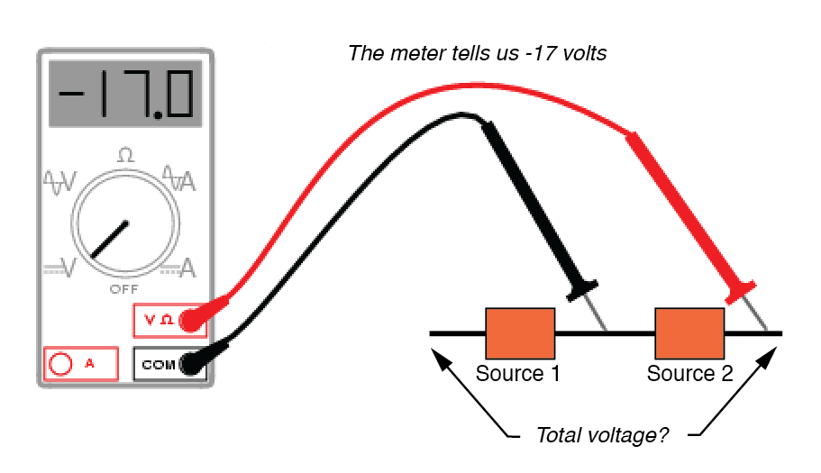
(–) Reading indicates black is (+), red is (–).
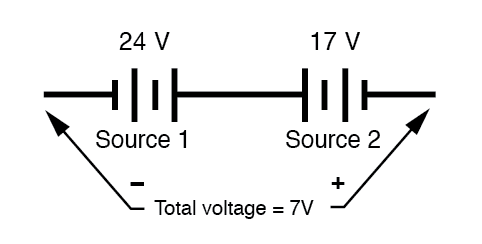
17 V source is polarized (+) to (–).
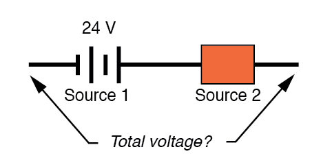
When two opposing batteries are connected in series, the net voltage equals the difference between their magnitudes: 24 V – 17 V = 7 V.
Polarity Markings in AC Circuits
In AC analysis, the sign of a voltage is replaced by its phase angle. Polarity marks on the schematic provide the reference point for that phase. If two AC sources are aiding, we add their complex phasors; if they oppose, we subtract.
Example:
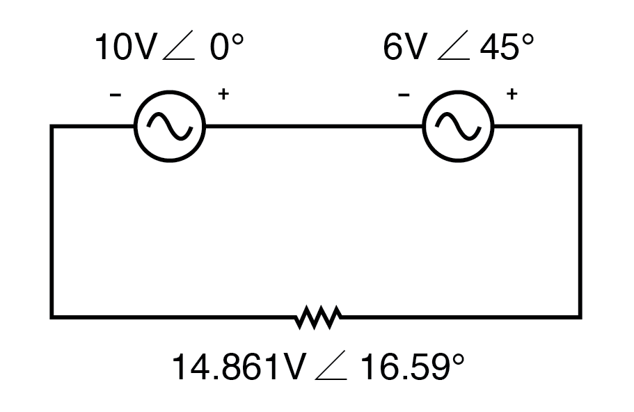
Phase angle substitutes for ± sign.
The two sources (10 V ∠0° and 6 V ∠45°) are aiding, so the total is 14.861 V ∠16.59°.
Reversing the polarity marks on the 6‑V source shifts its phase by 180°, but the resulting phasor sum remains unchanged.
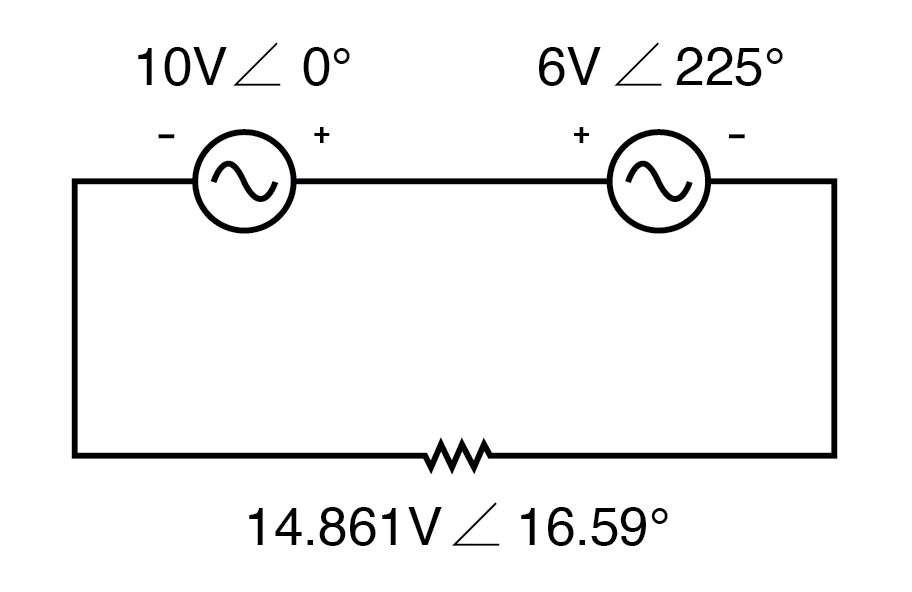
Reversing the voltmeter leads on the 6 V source changes the phase angle by 180°.
In contrast to DC batteries, AC voltage symbols have no inherent polarity; the markings must be added explicitly and must align with the specified phase angle.
Review
- Polarity markings on AC sources provide a frame of reference for their phase angles in circuit schematics.
Related Worksheet
- AC Network Analysis Worksheet
Industrial Technology
- Exploring Voltage Addition with Series Battery Connections
- Voltage Divider Lab: Design, Measurement, and Kirchhoff’s Voltage Law Verification
- Thermoelectricity: Understanding Thermocouples and the Seebeck Effect
- Potentiometric Voltmeter: Precise Voltage Measurement with Minimal Loading
- Build a Potato Battery: A Step‑by‑Step Guide to DIY Electrochemical Power
- Voltage Multipliers Explained: Doubler, Tripler, Quadrupler, and the Cockcroft–Walton Design
- Understanding Voltage Drop Polarity in Circuit Analysis
- Tachogenerators: Precision Speed Measurement for Industrial Motors and Equipment
- Understanding AC Waveforms: Sine Waves, Frequency, and Oscilloscope Basics
- The Ultimate 9V Voltage Regulator Guide: How to Use and Maximize Performance