


Voltage Multipliers Explained: Doubler, Tripler, Quadrupler, and the Cockcroft–Walton Design
A voltage multiplier is a specialized rectifier that produces a DC output that is an integer multiple of the AC peak input—commonly 2×, 3×, or 4×. In practice, a 100 V peak AC source can generate about 200 V DC with a doubler, or 400 V DC with a quadrupler, though real‑world loading will reduce these figures.
Types of Voltage Multipliers
Voltage Doubler
Most laboratory power supplies use a doubler to step a 120 V or 240 V AC source up to around 300 V DC. A full‑wave bridge configured as a doubler delivers the same DC voltage from either 120 V or 240 V mains, which then powers a switching regulator for lower voltages.
Half‑Wave Voltage Doubler
The half‑wave doubler combines a clamper and a half‑wave rectifier. The clamper charges capacitor C2 to the negative peak of the input (≈5 V minus diode drop), then the rectifier allows C2 to add to the generator voltage during the positive half‑cycle. The resulting output stabilizes at about 10 V (≈8.6 V with realistic diode drops).
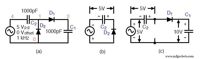
*SPICE 03255.eps
C1 2 0 1000p
D1 1 2 diode
C2 4 1 1000p
D2 0 1 diode
V1 4 0 SIN(0 5 1k)
.model diode d
.tran 0.01m 5m
.end
Illustration: v(4) is the input, v(1) the clamper stage, v(2) the half‑wave rectifier stage, and v(3) the final output.
Full‑Wave Voltage Doubler
By stacking two half‑wave rectifiers in series, the full‑wave doubler charges one capacitor on the negative half‑cycle and another on the positive half‑cycle. The two capacitors together provide a doubled voltage with higher ripple tolerance.
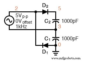
*SPICE 03273.eps
*R1 3 0 100k
*R2 5 3 100k
D1 0 2 diode
D2 2 5 diode
C1 3 0 1000p
C2 5 3 1000p
V1 2 3 SIN(0 5 1k)
.model diode d
.tran 0.01m 5m
.end
Result: v(5) reaches the full output within a single input cycle.
Deriving Full‑Wave Doublers from Half‑Wave Rectifiers
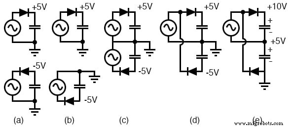
Combining two opposite‑polarity half‑wave rectifiers and re‑referencing the ground yields a ±5 V supply (≈±4.3 V with diode drops). The output across the two outputs is then 10 V.
Voltage Tripler
A tripler is essentially a doubler stacked on a half‑wave rectifier. The half‑wave stage adds ~5 V, the doubler adds ~10 V, producing a total of ~15 V (≈12.9 V with diode drops) relative to ground.
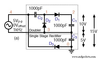
*SPICE 03283.eps
C3 3 0 1000p
D3 0 4 diode
C1 2 3 1000p
D1 1 2 diode
C2 4 1 1000p
D2 3 1 diode
V1 4 3 SIN(0 5 1k)
.model diode d
.tran 0.01m 5m
.end
Voltage Quadrupler
Stacking two doubler stages produces a quadrupler. Each doubler contributes ~10 V (≈8.6 V realistic), so the combined output is ~20 V (≈17.2 V). Two DC outputs are available: one at the intermediate doubler and one at the final stage.
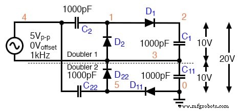
*SPICE 03441.eps
*C22 4 5 1000p
*C11 3 0 1000p
D11 0 5 diode
D22 5 3 diode
C1 2 3 1000p
D1 1 2 diode
C2 4 1 1000p
D2 3 1 diode
V1 4 3 SIN(0 5 1k)
.model diode d
.tran 0.01m 5m
.end
Waveforms show successive clamping at higher levels: v(5), v(4), and v(1).
Safety and Practical Considerations
- Typical simulation parameters (5 V, 1 kHz, 1 nF) produce microamp‑level currents; for milliamps of load current, use 0.1–1.0 µF capacitors on kHz circuits.
- For 50/60 Hz mains operation, capacitors should be several hundred to a few thousand µF to supply hundreds of milliamps.
- Always observe correct polarity and voltage rating on electrolytic capacitors—reverse polarity can cause explosions.
- Direct‑line powered circuits (no transformer) are hazardous; keep them in shielded enclosures and never breadboard without a safety guard.
Cockcroft–Walton Multiplier
The Cockcroft–Walton is a cascade of half‑wave doublers. With eight stages (x8), it can deliver ~30 V from a 5 V peak input, accounting for diode drops. Although each added stage yields less incremental voltage, the topology avoids the need for a high‑voltage transformer.
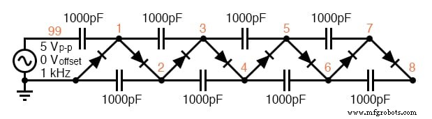
D1 7 8 diode
C1 8 6 1000p
D2 6 7 diode
C2 5 7 1000p
D3 5 6 diode
C3 4 6 1000p
D4 4 5 diode
C4 3 5 1000p
D5 3 4 diode
C5 2 4 1000p
D6 2 3 diode
D7 1 2 diode
C6 1 3 1000p
C7 2 0 1000p
C8 99 1 1000p
D8 0 1 diode
V1 99 0 SIN(0 5 1k)
.model diode d
.tran 0.01m 50m
.end
Real‑world applications include photomultiplier tubes (up to 2000 V) and ion generators for air purification. The series of taps replaces resistive dividers, reducing heat and improving efficiency.
Key Takeaways
- A voltage multiplier scales AC peak voltage to a higher DC level.
- The simplest is the half‑wave doubler; full‑wave doublers improve ripple performance.
- Triplers combine a doubler with a peak detector; quadruplers stack two doublers.
- Cockcroft–Walton multipliers provide scalable high voltage without costly transformers.
Related Worksheets
- Summer and Subtractor OpAmp Circuits Worksheet
Industrial Technology
- Essential DC Circuit Equations and Laws for Engineers
- Binary Signals and Logic Gates: Foundations of Digital Electronics
- Passive Averager and Op‑Amp Summer Circuits: From Averaging to Addition
- Understanding Voltage and Current: The Foundations of Electrical Flow
- Capacitors & Calculus: How Voltage Change Drives Current
- Advanced Analysis of DC Reactive Circuits with Non‑Zero Initial Conditions
- Understanding Polarity and Phase in AC Circuit Analysis
- Three‑Phase Y and Delta Configurations: Design, Analysis, and Reliability
- The Ultimate 9V Voltage Regulator Guide: How to Use and Maximize Performance
- Comprehensive Guide to the LM7815 Voltage Regulator: Usage, Features & Applications