


Optocoupler Basics: Function, Types, and Practical Applications
What is An Optocoupler,As a PCB designer, engineer, or hobbyist, you have a wide variety of switches, relays, and couplers to customize your PCB. With all the PCB components and options available on the market, it’s hard to decide which will suit your project the best.
For instance, you may be wondering what an optocoupler does and how it is different from any other relay. This is what the following guide hopes to elucidate. In it, we’ll explore the optocoupler, its various types, and how it can benefit you and your project.
What is an Optocoupler
Optocouplers go by many names. You may refer to it as an optoisolator, photocoupler, optical coupler, optical isolator, or just optocoupler. Some people may even refer to them as options. Nevertheless, optocouplers are integrated electronic components. Generally, the most basic types consist of a rectangular body with four pins. Each pin is a subcomponent. The first pin is the anode, the second is the cathode, the third is the collector, and the fourth is the emitter.
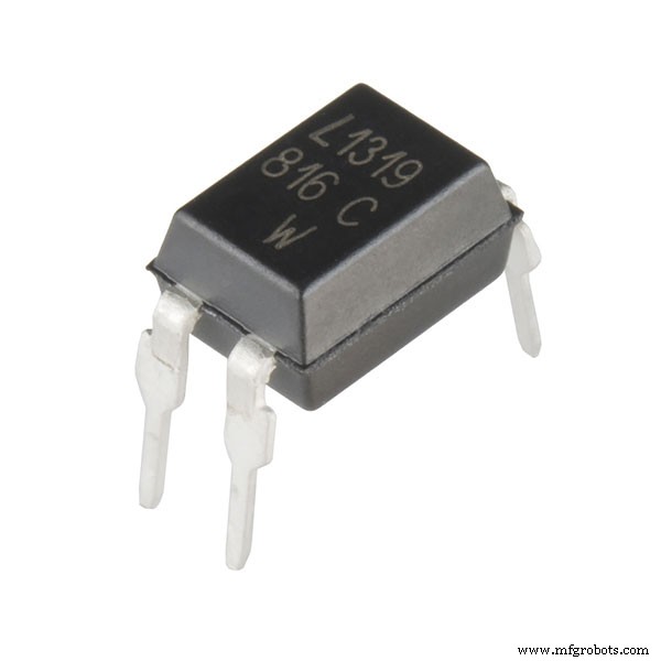
LTV-816 1 channel opto-isolator
Source: Wikimedia Commons
Additionally, there is a circular indentation on the corner of the main body near the first pin. It allows us to identify the different pins. The body also contains some text bearing the optocoupler’s part number. Accordingly, we use it to identify the type of optocoupler and also find the manufacturer’s datasheet.
Nevertheless, the optocoupler is essentially a solid-state relay that interconnects two separate electronic circuits. The first circuit will connect across the first two pins (pin 1 and 2), while the second circuit will connect to the last two pins (pin 3 and 4). This allows the first circuit to control the second circuit.
It’s easy to mistake an optocoupler with an Integrated Circuit/microchip (IC) because of how it looks. This is especially true for TRIAC optocouplers.
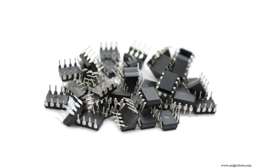
Electronic Microchips in a white background
How Does an Optocoupler Work?
We can use the optocoupler to transfer electronic signals between two isolated circuits. This is one of its more important attributes. Sometimes voltage spikes and noise may occur in one circuit. Without the optocoupler isolating the circuits, these disruptions may spread to the second circuit and cause destruction. The optocoupler prevents this damage from occurring in both circuits.
Additionally, the optocoupler will only allow electrons to flow in one direction because of its semiconductor materials. Consequently, this allows the two interconnected circuits to use different voltages and currents.
Furthermore, it allows you to expand your device’s capabilities. This is largely due to how it facilitates galvanic isolation between two separate circuits. For instance, we could add a transistor to the second circuit without interfering with the first in a two-circuit configuration. This would allow you to control even higher amounts of voltage and current. Moreover, it could potentially allow you to automate the circuit control by adding electronic components.
The Structure of an Optocoupler
Optocouplers come in a wide variety of types and configurations. However, to make things easier to understand, we’ll focus mainly on the phototransistor version.
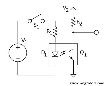
Phototransistor optocoupler circuit diagram
Source: Wikimedia Commons
The above diagram illustrates a phototransistor connecting two circuits. If you look carefully at the phototransistor portion of the diagram, you’ll notice that there is an LED symbol on the left:
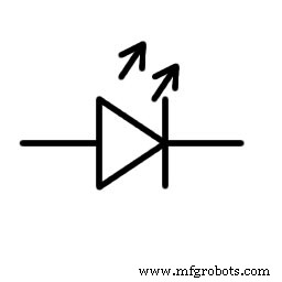
Image of LED symbol
Source: Wikimedia Commons
Contrastingly, there is a transistor symbol right:
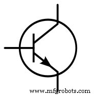
Image of transistor symbol
Source: Wikimedia Commons
We can easily spot the above figures that a phototransistor is a modified version of a normal transistor. Moreover, you can understand why we call the (third and fourth) terminals on the transistor side collectors and emitters. Furthermore, you can also see why we call the first and second terminals anode and cathodes.
Transistors generally have three terminals. However, there is a small difference here. The base pin in a normal transistor circuit is missing from the phototransistor circuit. This is because the transistor in an optocoupler works slightly differently. Instead of using electronic signals from the base pin, the transistor in an optocoupler uses light from the LED.
The light shines from the LED and hits the transistor, switching it on and allowing current to flow in the main electrical circuit. They react to optical input as opposed to just electrical input current. Optocouplers come in two common topologies. The inner components can either sit on top of each other or next to each other.
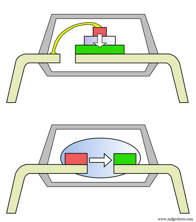
Optocoupler topologies
Source: Wikimedia Commons
While we can’t see the inner workings of the phototransistor (unless it’s translucent), we can create our very own using a simple circuit. We’ll explore that further down this guide. But first, let’s explore the other optocoupler types.
Optocoupler Types
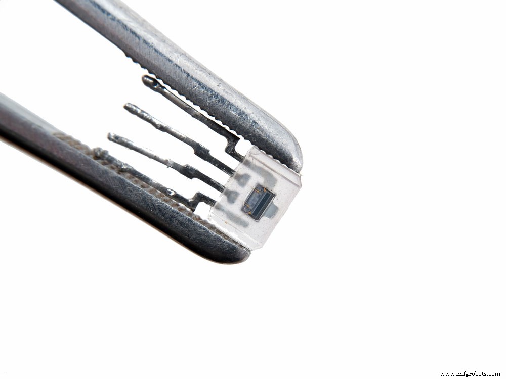
Optocoupler held between a pair of tweezers.
There are six most common types of transistors. They are:
- Resistive Optocoupler: These were the earliest optocouplers. They use incandescent light bulbs, neon lamps, and GaAs infrared LEDs as light sources. Additionally, they use cadmium sulfide for transistor material. People also refer to these types of optocouplers as vactrols.
Because they’re an older photosensitive device, they’re a bit slower than more modern forms of optocouplers. Consequently, this is why they are nigh obsolete. - Diode Optocoupler: Diode optocouplers use gallium arsenide infrared LEDs for light sources and silicon photodiodes as receptors. This makes them the fastest type of optocouplers – especially when they utilize PIN diodes.
- Transistor Optocoupler: Just like diode optocouplers, they also use GaAs infrared LEDs as light sources. However, they either use bipolar silicon phototransistors or Darlington phototransistors as sensors. This makes their transfer rates and response times faster than resistive optocouplers but slower than diode optocouplers.
- Opto-isolated SRC: Opto-isolated SRCs use infrared LEDs along with silicon-controlled rectifiers. Their transfer speeds may vary. However, they’re not as fast as diode-based optocouplers in any configuration. Nevertheless, they still have a decent response time and transfer rate.
- Opto-isolated TRIAC: These types of optocouplers use a triode for alternating current (TRIAC) as a sensor type. This is in addition to their GaAs infrared LED as a light source. While they don’t have fast transfer rates, they have very high current transfer ratios.
- Solid-state relay: Solid-state relays use a stack of GaAs infrared LEDs as light sources. Additionally, they use a stack of photodiodes that either drives a pair of MOSFETS or a singular IGBT as sensors. They can have very high transfer speeds and unlimited current transfer ratios.
How to Create a Simple Optocoupler Circuit
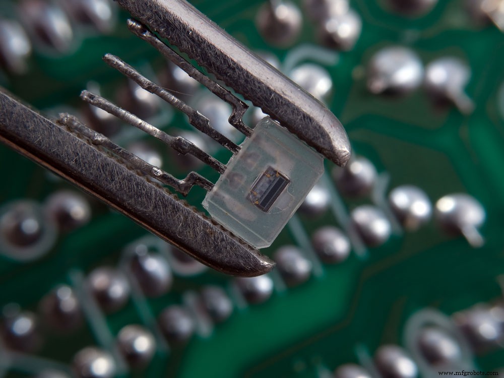
Optocoupler held between a pair of tweezers in front of a PCB
Part List:
- 50-100K Ohm Light Dependent Resistor (LDR)
- 3V 0.02A White Light Emitting Diode (LED)
- 2V 0.02A Red Light Emitting Diode (LED)
- 9V battery x 2
- Switch
- 300 Ohm Resistor
- 150 Ohm Resistor x 2 (or 300 Ohm resistor)
Explanation and instructions:
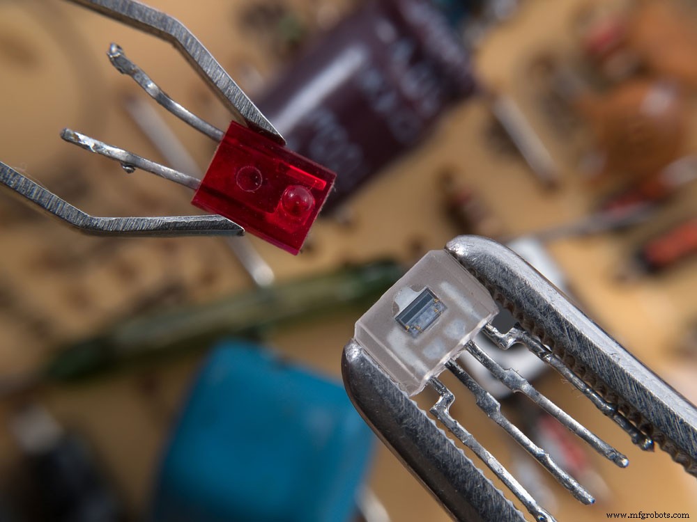
Red LED and optocoupler
This simple optocoupler uses a simple light-dependent resistor (LDR) and a white LED. The LDR varies its load resistance based on the light exposure. Thus, in darkness, it has a very high resistance. Inversely, when we expose it to bright light, it has a meager resistance. In this context, it will function as our photodiode.
In the primary circuit, we will need a white LED that has a voltage drop of 3 volts and uses 0.02 amps. Next, we will employ a 9-volt battery as a power supply and control the circuit using a switch. Because the white LED light requires a 3-volt current, we’ll need a resistor with a 6-volt drop. Thus, the resistor must have 300 Ohms of resistance ( (9V – 3V) ÷ 0.02A).
So your primary circuit will consist of the battery, which positively connects to the switch, resistor, and the white LED light. You can use a breadboard or wire to connect the components. Altogether, this will act as our control circuit.
We’ll have a red LED with a voltage drop of 2 Volts and an electric current of 0.02 Amperes on the secondary circuit.
We’ll use it as an indicator to show when the circuit is working. Additionally, we’ll connect the LDR to this circuit. Obviously, the LDR needs to sit adjacent to the white LED light.
The LDR will provide a resistance of roughly 70 Ohms when we expose it to the light from the LED. You’ll need to connect the LDR to the red LED. To power the secondary circuit, we’ll employ another 9-Volt battery. Again, we’ll need a resistor to drop the voltage so the LED can work effectively. We suggest using two 150 Ohm resistors. However, one 300 Ohm resistor will be fine too.
Nevertheless, once you’re done constructing the circuit, you’ll need to wrap some black tape around the LDR and white LED. You must make sure that you connect them. This will block the ambient light in the room. Alternatively, you can test the circuit in a completely dark room.
When you press the primary circuit (input circuit) button, the white LED will turn on. Then it will shine a light against the LDR, which will turn the red LED on in the output circuit. The light from the white LED functions like an electrical signal in a switch. This project is simple enough to illustrate the inner workings of an optocoupler. However, you can improve it by implementing an infrared emitter along with a receiver. Instead of visible light, this project would use infrared light.
Optocoupler Applications
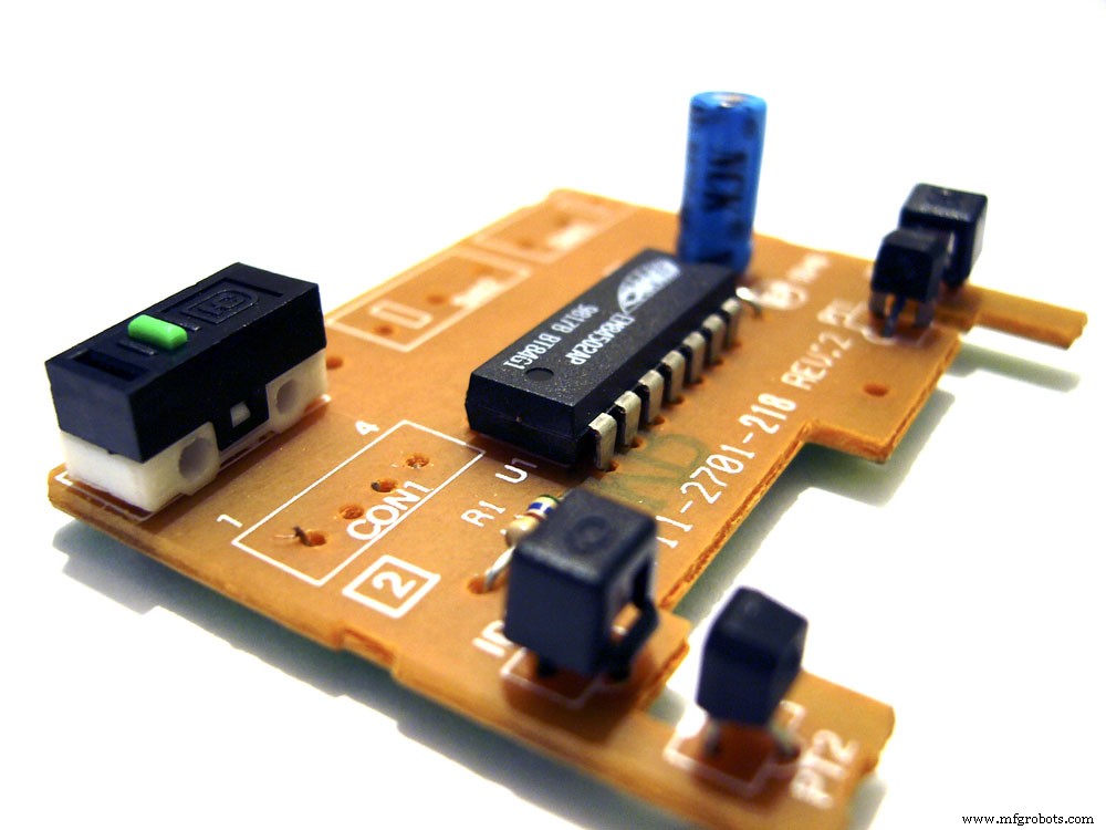
Small PCB assembly with IC, capacitor, optocoupler, and other semiconductors
Now that we understand how optocouplers work, now we can explore where we can apply them. We can use optocouplers as simple light-activated switches. However, what electronic equipment and devices would suit them best? Here’s a list of where we could use optocouplers:
- Solenoid controls
- Motor controls
- Incandescent lamp dimmers
- Microprocessors
- Lamp ballasts
- AC detection
- Voltage isolation
- Electromagnetic switch
- Microcontrollers
Optocoupler Benefits
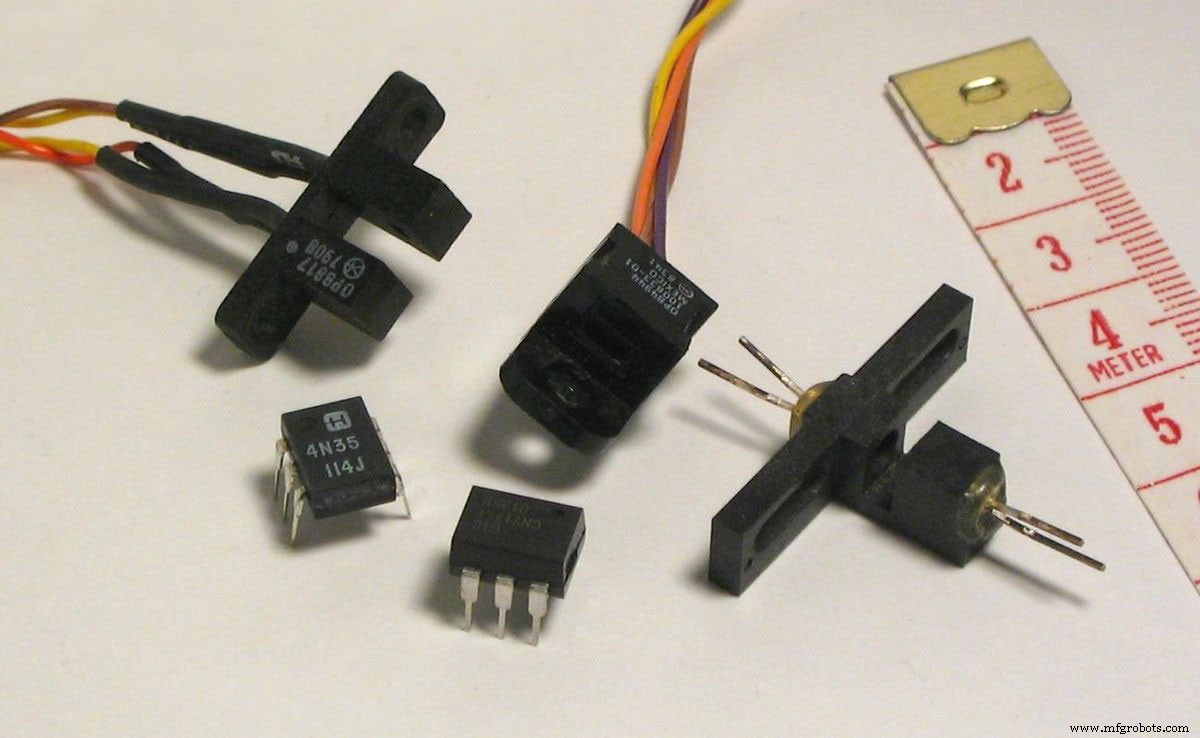
A set of optocouplers
Why would you want to use optocouplers instead of electromechanical relays or switches? Here are just a few of the advantages:
- They facilitate a one-way conveyance of electrical signals
- Optocouplers make your projects more reliable by making them resistant to interference
- They can facilitate electrical isolation between multiple circuits
- Optocouplers can separate the input and output sections of your project, thus making it easier to troubleshoot
- They reduce external output signals on the input section of your circuit
- Optocouplers allow you to control large AC circuits by using small digital signals
- Allows you to transfer an analog signal between two separate circuits
- They allow you to interface high-voltage components with low-voltage devices
- Optocouplers can help reduce or completely eliminate electrical noise from signals
- Allows you to design and build electronic devices that are more resistant to power supply spikes, voltage surges, and lightning strikes
Conclusion
In the above text, we provided an easy-to-understand and in-depth guide on optocouplers. If you’ve reached this section of the guide, you have a deeper understanding of optocouplers. Nevertheless, we hope that you’ve found this guide to be helpful. As always, thank you for reading.
Industrial Technology
- Plasma Cutting Explained: How It Works and Key Benefits
- Electrochemical Grinding Explained: How It Works & Key Benefits
- Understanding Inventory Accounting: Methods, Types, and Business Impact
- Understanding Ransomware: How It Works & Why It Matters
- Understanding LED StarBoard: Design, Function, and Heat Dissipation Benefits
- Vacuum Tube Diodes Explained: Function, History, and Modern Applications
- Refrigerator Alarm: The Smart Solution to Keep Your Food Fresh
- LED Fader Circuit Explained: How It Works & Why It Matters
- Neon Lamp Circuit Explained: Function, Applications, and Benefits
- NFC Antennas Explained: How They Work and Why They Matter