


LED Fader Circuit Explained: How It Works & Why It Matters
In recent times, LED lights have seen a rapid increase in use because of how cheap and durable they are. Plus, LEDs don’t consume as much energy as other light sources.
Also, you can view different applications like decorations for houses or offices, emergency lights, automobile daytime running lights, regular lamps, and many more.
The fading of LEDs is one of such crucial applications. Here, you can configure your LED lights to heighten and reduce their intensity for different purposes.
So, in this article, we will tell you everything you need to know about fading LEDs and how to create a simple LED fader circuit with a breadboard, PCB, IC 555 timer.
Ready? Let’s start!
Up-Down Fading LED Lights Circuit Principle

Led shining diodes
An up-down fading LED circuit consists mainly of a capacitor and a transistor. Plus, the LED operates in forwarding bias conditions. In other words, the LED glows when you connect the positive terminal to the positive end and the negative end to the battery’s negative terminal.
For this up-down fading circuit, the LED will only conduct when you ground the negative terminal while the positive terminal receives some voltage. So, when you press the button, the capacitor will begin charging and discharging. And this process makes the LED fade down, up, and down.
How to Produce Your Fade on LED Lights?
Here, we will discuss how to create a fade-on LED light circuit using three methods: with a breadboard, PCB, and IC 555 timer.
Fade on LED Light Using a Breadboard
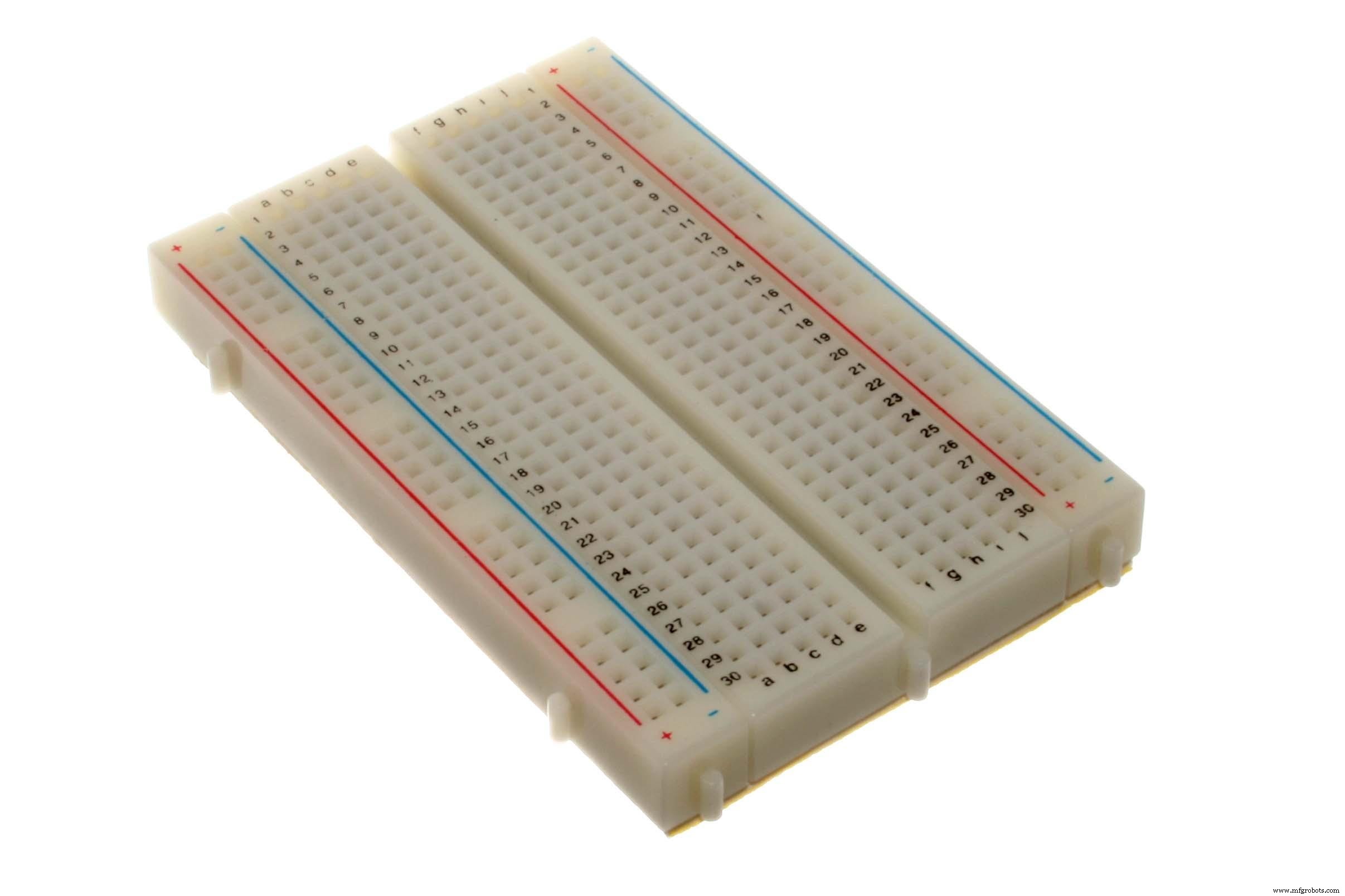
Breadboard
This circuit follows the up-down fading principle we discussed earlier. With it, you can easily fade your LEDs up and down. Here’s the circuit diagram we’ll be learning:
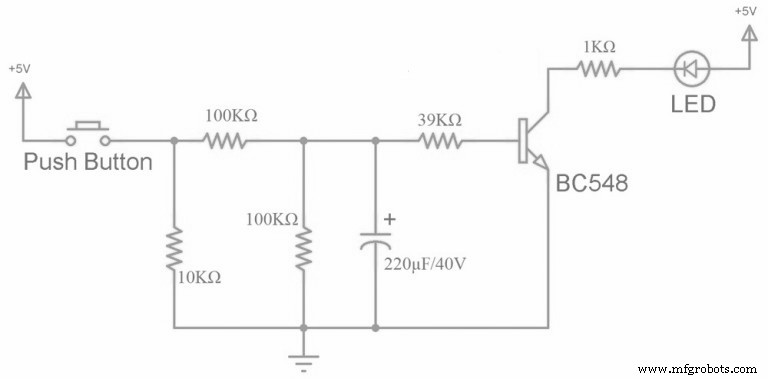
Circuit Diagram 1
Required Components
- 220μF capacitor
- (2) 100KΩ resistors
- 10KΩ resistors
- 39KΩ resistors
- 100Ω resistors
- LED
- Connecting wires
- 5V power supply
- Mini breadboard
- BC 548 (an NPN transistor)
- On/off switch (push button)
Construction
For the circuit, you should connect the power supply to the on/off switch (push button). Also, connect a 10KΩ resistor after the button so the button can stay in pull-down mode. For this reason, the button starts low and becomes high when you press it.
Next, connect the switch to a 100KΩ resistor. This resistor will have the task of charging the 220μF capacitor. Also, connect the 39KΩ resistor before the transistor. The capacitor will discharge through this resistor.
Also, connect the second 100KΩ resistor correspondent to the capacitor. It will allow the 39KΩ resistor receives most of the capacitor’s discharge.
Additionally, the transistor we’re using is a BC548 series NPN transistor. Plus, the transistor starts in an off state.
Also, the voltage will only flow to the collector if the base region receives some voltage. The base of the transistor requires a minimum voltage of 0.7V.
When you apply this voltage to the base, the transistor begins conducting.
As a result, the voltage flows from the emitter to the collector.
Finally, you can place a PN junction diode like 1N4007 between the 100KΩ resistor and capacitor to allow the capacitor’s discharge to only flow through other resistors.
How to Operate a Fade on LED Light Using Breadboard
First off, turn on the circuit.
Then, press the button and allow the LED to fade up, which increases its intensity.
Note that voltage flows the diode and a series of 100KΩ resistors when you press the button.
Afterward, the linked capacitors charge up and distribute current to the transistor’s base, which starts conducting. Then, the emitter’s voltage transmits to the grounder collector and negative LED terminal.
Finally, you can release the switch for the LED to fade out, the capacitor discharges.
Limitations
- The color of LEDs can change due to temperature and age
- You must provide the correct voltage otherwise you risk damaging your LEDs
Fade on LED Lights Using PCB
For this circuit, we will use software to simulate the circuit diagram before designing it. So, for simulating the circuit, we will use the Proteus design suite.
Once you download and install the Proteus software, open a new schematic by clicking on the ISIS icon on the menu.

Proteus Design Suite Guide
When your new schematic pops up, click on the P icon on the side menu to open a box. Here, you can choose all the components you need.

Proteus Software Guide 2
Next, insert the name of the components you need for your circuit so they can appear on a list on the right side.

Proteus Software Guide 3
So, once you’re done simulating the circuit, you should have a diagram like this:
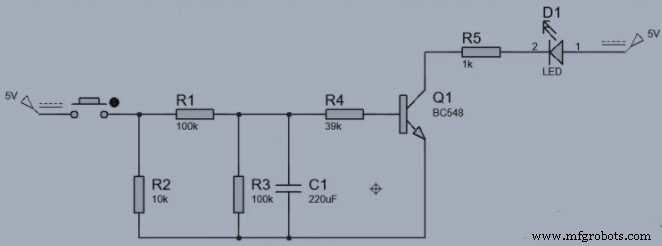
Circuit diagram 2
Working Principle
The LED in this circuit doesn’t operate in reverse biased mode, rather it operates in forward-biased mode. In other words, it only works when connected to the power supply’s positive terminal. Also, it features a push button that starts the charging and discharging process of the capacitor when pushed or released.
Required Components
- 220uF Electrolytic Capacitor
- 100k Ohm Resistor (2)
- 10k Ohm Resistor (1)
- 39k Ohm Resistor (1)
- 100 Ohm Resistor (1)
- BC 548 NPN Transistor (1)
- LED’s
- Push Button Switch
- Jumper Wires
- Battery Clip
- Printed Circuit Board
- FeCl3
- Soldering Iron
- Hot Glue Gun
Construction
First, get your PCB to make your circuit layout. So, print your simulated circuit on a piece of butter paper and place it on the PCB, and iron until it prints on the board. This process will take up to five minutes.
Note: Before you place your butter paper, reduce the copper layer on your board with a PCB scrapper.
When you’re done printing, dip the PCB in some FeCI3 hot water solution to get rid of excess copper. Next, scrap your PCB with your scrapper again and drill holes in the respective places.
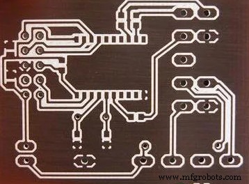
PCB Layout
Now, solder all components on the board according to your circuit simulation. Finally, check if the circuit works. If it doesn’t, remove and re-connect the components. Also, use hot glue for positive and negative battery terminals so they won’t detach from the circuit.
How to Operate
This circuit works similarly to the fade-on circuit with a breadboard.
Fade On Circuit with an IC 555 Timer
Here, we’ll learn how to produce a fade-on LED circuit with a 555 timer. Here’s the circuit diagram we’ll be learning:
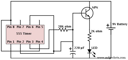
Circuit Diagram 3
Components Required
Here are the components you need for this circuit:
- 555 timer IC
- LED
- 10uF Capacitor
- BC547 transistor
- Battery (9v)
- 100k, 470-ohm resistor
- Jumper wires and breadboard
IC 555 Timer
Working Principle
Building a slow fade LED circuit with a 555 timer is simple. Here we’ll use the IC 555 in astable mode and a transistor to amplify the current. The IC 555 in astable mode will oscillate at a specific frequency.
In other words, the output of PIN 3 periodically goes high and low. So, in this circuit, when PIN 3 goes high, the transistor will amplify the current. Thus, it allows the current flow to the capacitor and charges it to 2/3 VCC. During this process, the LED emits light.
After this, PIN 3’s output becomes low and switches off the transistor. Thus, discharging the capacitor through the collector-emitter junction. Also, this gives the LED the fading effect.
Construction
As we mentioned earlier, building a fade circuit with a 555 timer is easy. All you have to do is follow the circuit diagram. Then ensure the 555 timer is in the right position and all polarized components are in the right position.
LED Fader Circuit–Applications
Here are some applications of the up-down fading LED lights circuit:
- Fading LED lights circuits work in home applications
- Useful in shopping malls for fading lights in areas with no people
- You can use fading LED lights as indicators in cars
LED Fader Circuit– Rounding Up
Over the years, LED lights have enjoyed a rise in popularity.
But, it’s not only because of how cheap or durable they are.
Instead, it’s because of how many colorful projects you can achieve with any LED light circuit.
There’s hardly any limit to what you can do with LEDs and fading LEDs. You can create beautiful decorations or get alerts from your car.
Well, that rounds up this article. If you have any suggestions or questions, feel free to contact us and we’ll be happy to help.
Industrial Technology
- Plasma Cutting Explained: How It Works and Key Benefits
- Electrochemical Grinding Explained: How It Works & Key Benefits
- Understanding Ransomware: How It Works & Why It Matters
- Understanding LED StarBoard: Design, Function, and Heat Dissipation Benefits
- Optocoupler Basics: Function, Types, and Practical Applications
- Vacuum Tube Diodes Explained: Function, History, and Modern Applications
- Refrigerator Alarm: The Smart Solution to Keep Your Food Fresh
- Neon Lamp Circuit Explained: Function, Applications, and Benefits
- Build a Pulsing LED Circuit: Step‑by‑Step Guide to Stunning Light Effects
- NFC Antennas Explained: How They Work and Why They Matter