


Three‑Phase Y and Delta Configurations: Design, Analysis, and Reliability
Three‑Phase Wye (Y) Connection
Three‑phase power systems can be built by joining three voltage sources at a common point – the classic Y (or star) configuration.
This arrangement places one end of each source on a shared node, while the other ends radiate to the load. (Figure below)
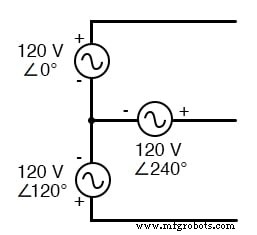
Three‑phase Y connection: three voltage sources sharing a common point.
Visualizing each voltage source as a coil (alternator or transformer winding) makes the Y layout unmistakable (see figure).
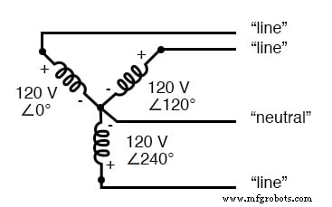
Four‑wire Y connection: a neutral (common) fourth conductor ties the three windings together.
The conductors that carry current from the windings to the load are called lines, while the windings themselves are the phases.
A neutral wire may or may not be present at the junction. When included (Figure below), it provides a path that protects against open‑circuit failures in one phase.
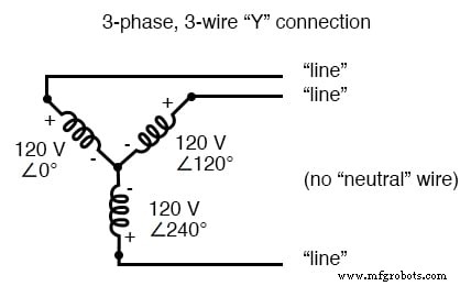
Three‑wire Y connection: no neutral wire is used.
Voltage and Current Values in Three‑Phase Systems
When measuring in a three‑phase system, it’s crucial to specify the reference point.
- Line voltage – the voltage between any two line conductors. In the circuit above, the line voltage is approximately 208 V.
- Phase voltage – the voltage across a single component (source winding or load). For the same circuit, the phase voltage is 120 V.
- Line current – current flowing through any one line conductor.
- Phase current – current through a single component.
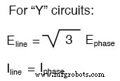
In a balanced Y configuration, line voltage equals phase voltage multiplied by √3, while line current equals phase current:
Three‑Phase Delta (Δ) Configuration
The Delta layout, named for its triangular geometry, connects the three voltage sources end‑to‑end without a common neutral. (Figure below)
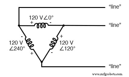
Three‑phase Δ connection: no common neutral.
At first glance, connecting three sources in a loop might seem to create a short‑circuit, but phase angles prevent any circulating current.
Kirchhoff’s Voltage Law in Delta Connections
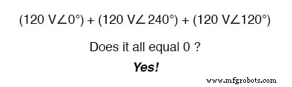
A quick KVL check confirms that the three vector voltages sum to zero, meaning no net driving force exists around the loop.
For example, starting at the top winding and moving counter‑clockwise:
Alternatively, break the loop at one junction and verify the voltage across the break is zero:
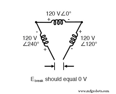
Voltage across an open Δ is zero – no circulating current.
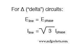
When the Δ‑connected source is complete, the line voltage equals the phase voltage, whereas the line current becomes the vector sum of two phase currents. Consequently:
Delta Connection Example Circuit Analysis
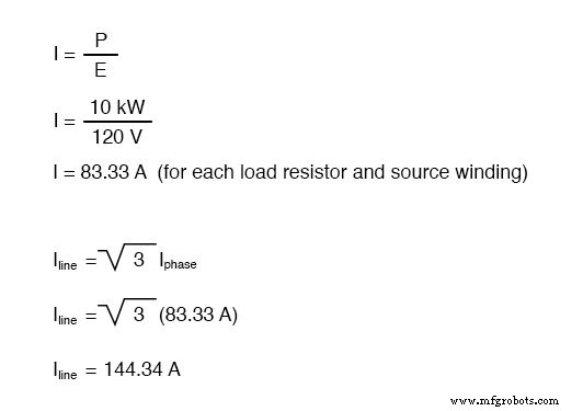
Consider the following Δ‑loaded source (Figure below). Each load resistance receives 120 V from its respective source winding, yielding a phase current of 83.33 A.
The load on the Δ source is wired in a Δ.
Thus, each line current equals 144.34 A, noticeably higher than in the Y‑connected case, yet still efficient for delivering the same 30 kW at 120 V conductor‑to‑conductor.
Advantages of the Delta Three‑Phase System
- Delta systems eliminate the need for a neutral wire, simplifying the cable bundle and reducing material costs.
- They offer superior fault tolerance: if one winding fails open, the remaining windings maintain line and load voltages, only increasing phase currents slightly.
- Delta’s higher line currents require thicker conductors, but the overall copper weight remains lower than a comparable single‑phase system.
- Y systems are preferred when dual voltages (e.g., 120/208 V) or lower line currents are required.
In the event of a source winding failure, the Δ configuration sustains full load voltage. For Y‑connected sources, the failure can halve the voltage on two loads and drop the third entirely.
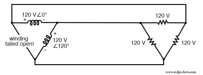
Δ source: open winding leaves line voltage at 120 V and phase voltage unchanged.
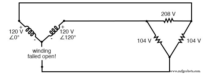
Y source: open winding halves voltage on two loads and removes power from the third.
Review
- Lines are the conductors connecting the three points of a source or load.
- Phases are the individual components (windings or impedances) that comprise the system.
- Line voltage = voltage between any two lines.
- Phase voltage = voltage across a single component.
- Line current = current through a line; phase current = current through a component.
- Balanced Y: line voltage = √3 × phase voltage; line current = phase current.
- Balanced Δ: line voltage = phase voltage; line current = √3 × phase current.
- Δ sources offer greater reliability on winding failure, but Y sources reduce line current for the same power output.
Related Worksheets
- Delta and Wye 3‑Phase Circuits Worksheet
Industrial Technology
- Essential DC Circuit Equations and Laws for Engineers
- Binary Signals and Logic Gates: Foundations of Digital Electronics
- Essential Transistor Ratings and Package Types for Bipolar Junction Transistors
- Single‑Ended vs. Differential Amplifiers: Design, Operation, and Applications
- Passive Averager and Op‑Amp Summer Circuits: From Averaging to Addition
- Understanding Differentiator and Integrator Op‑Amp Circuits
- Understanding Voltage and Current: The Foundations of Electrical Flow
- Capacitors & Calculus: How Voltage Change Drives Current
- Advanced Analysis of DC Reactive Circuits with Non‑Zero Initial Conditions
- Three‑Phase Power Systems: Fundamentals and Benefits