


Three-Phase Transformer Circuits: Design, Wiring, and Practical Applications
Three‑phase power is the backbone of modern electric grids, and the transformers that step its voltage up or down are equally critical. While a single‑phase transformer can be ganged together to bridge two three‑phase systems, dedicated three‑phase transformers offer a more efficient solution—using less material, occupying less space, and weighing less than a modular stack.
Three‑Phase Transformer Windings and Connections
A typical three‑phase transformer consists of three independent primary‑secondary winding pairs, each wound around one leg of a shared iron core. The result is essentially three single‑phase transformers sharing a common core, as illustrated below.
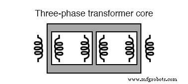
Three‑phase transformer core – three sets of windings.
The primary and secondary sets can be connected in either Delta (Δ) or Wye (Y) configurations. The four possible pairings are:
- Y – Y
- Y – Δ
- Δ – Y
- Δ – Δ
Choosing Y or Δ depends on the application: Y connections provide multiple voltage options (line‑to‑neutral) and enable a neutral conductor; Δ connections offer higher fault tolerance, since a single open winding still allows the other two to maintain full line voltages.
Correct winding phasing—indicated by the dots that mark polarity—is essential. The phase relationships for Δ and Y are illustrated below.
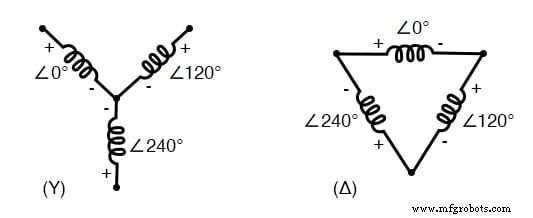
Y: the center point must connect either all ‘+’ or all ‘−’ poles. Δ: the winding polarities must be complementary (+ to −).
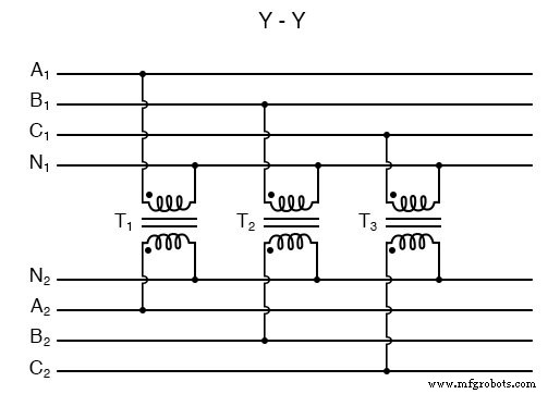
Phase Wiring for “Y‑Y” Transformer
When both primary and secondary windings are wired as Y, each winding end marked with a dot connects to the corresponding phase (A, B, C), while the non‑dot ends join to form the center of each Y. This configuration supports neutral conductors (N1 and N2) on both sides.
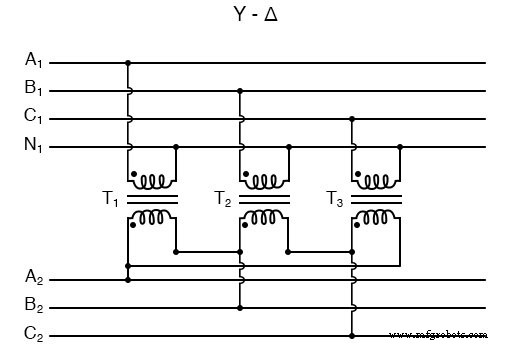
Phase Wiring for “Y‑Δ” Transformer
In a Y‑Δ transformer, the primary side remains Y‑connected, while the secondary side forms a Δ loop. The dot side of one winding connects to the non‑dot side of the next, chaining the three windings together.
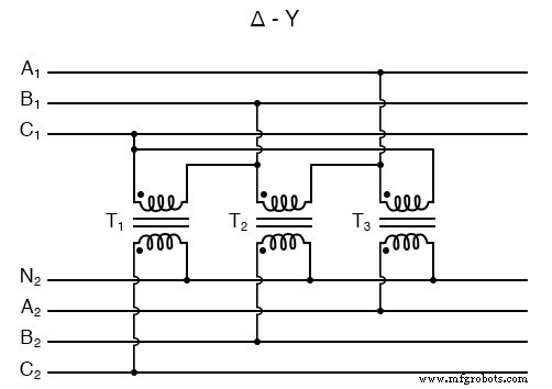
Phase Wiring for “Δ‑Y” Transformer
A Δ‑Y transformer supplies a secondary system that requires line‑to‑neutral voltages from a source lacking a neutral. The Δ primary feeds a Y‑connected secondary.
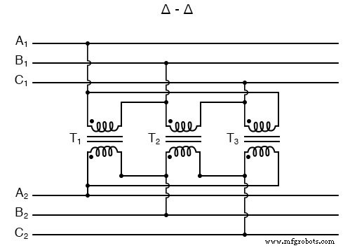
Phase Wiring for “Δ‑Δ” Transformer
When no neutral is needed on the secondary side, a Δ‑Δ configuration is preferred for its inherent reliability.
Phase Wiring for “V” or “Open‑Δ” Transformer
Some designers opt for a V or open‑Δ arrangement—using only two transformers—to supply two‑phase power. Each transformer is oversized to handle the full load, yielding savings in size, weight, and cost. However, the fault tolerance of a full Δ‑Δ system is lost.
Real‑Life Example
The Grand Coulee hydroelectric dam in Washington state features a bank of step‑up transformers grouped in threes. The green units are wired in a Y configuration on the secondary side, as evidenced by a single high‑voltage insulator per transformer—indicative of a neutral‑point connection.
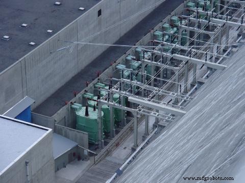
These transformers are crucial for stepping generator output to transmission voltages, ensuring reliable power delivery across the grid.
RELATED WORKSHEETS:
- Delta and Wye 3‑Phase Circuits Worksheet
Industrial Technology
- Foundations of DC Circuits: Understanding Direct Current and Core Electrical Concepts
- Understanding AC Circuits: A Beginner's Guide
- Rectifier Circuits: From Half‑Wave to Polyphase Full‑Wave Designs
- Understanding Clipper Circuits: Theory, Simulation, and Practical Applications
- Clamper Circuits – DC Restorers for Composite Video
- Crystal and Transistor Radio Circuits: From Basic Detectors to Integrated AM/FM Receivers
- Analog vs. Digital Computational Circuits: A Practical Guide
- Control Circuits: Fundamentals, Applications, and Best Practices
- RF Transformers: Design, Function, and Key Applications
- Optimizing Power Systems: Parallel Operation of Single‑Phase and Three‑Phase Transformers