


Understanding Harmonics in Polyphase Power Systems: Causes, Effects, and Mitigation Strategies
Harmonics—integer multiples of the fundamental frequency—are a natural consequence of non‑linear load behavior in AC power systems. Although a clean sine wave from a generator ideally contains no harmonic content, real‑world devices distort this waveform, generating measurable harmonic currents that can impact system performance.
Non‑Linear Loads and Harmonic Generation
Devices such as gas‑discharge lamps, semiconductor power controls (diodes, transistors, SCRs, TRIACs), transformers, and electric motors introduce non‑linearities. The current drawn by these components does not follow the applied voltage proportionally, producing non‑sinusoidal waveforms. Even incandescent lamps, whose filament resistance varies with temperature, exhibit a slight non‑sine current shape.
When a waveform is symmetrical about its centerline, only odd harmonics appear—1st, 3rd, 5th, etc.—while even harmonics are largely absent. This symmetry is common in most industrial loads, so the 2nd, 4th, 6th… harmonics are typically negligible.
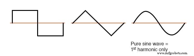 Symmetrical waveforms—odd harmonics only.
Conversely, nonsymmetrical waveforms generate both odd and even harmonics, as illustrated below.
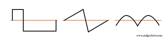 Nonsymmetrical waveforms—even harmonics present.
Implications of Harmonic Currents
Even in single‑phase systems, harmonics increase transformer core losses through eddy currents, leading to overheating. In polyphase networks, the situation is more complex. Triplen harmonics (3rd, 9th, 15th…), being integer multiples of the fundamental, add constructively in the neutral conductor of a balanced Y‑Y system, potentially causing neutral overheating—a critical safety concern because neutral conductors lack overcurrent protection.
SPICE Modelling of Harmonic Effects
Simulating nonlinear loads in SPICE offers intuitive insight without heavy mathematical analysis. Below are key configurations and their outcomes.
1. Linear Single‑Phase Load
Base circuit: 120‑V, 60‑Hz source, 1 kΩ load, with 1 Ω source and line resistances for measurement.
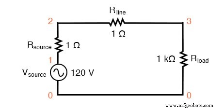 SPICE circuit with a single sine‑wave source.
linear load simulation
vsource 1 0 sin(0 120 60 0 0)
rsource 1 2 1
rline 2 3 1
rload 3 0 1k
.options itl5=0
.tran 0.5m 30m 0 1u
.plot tran v(2,3)
.four 60 v(2,3)
.end
Fourier analysis confirms a single fundamental at 60 Hz (0.1198 A) with negligible higher‑order components, yielding 0 % total harmonic distortion (THD).
2. Single‑Phase Load with 3rd‑Harmonic Current Source
Adding a 50 mA, 180 Hz (3×fundamental) current source in parallel with the 1 kΩ resistor introduces a clear 3rd‑harmonic signature.
Nonlinear load simulation
vsource 1 0 sin(0 120 60 0 0)
rsource 1 2 1
rline 2 3 1
rload 3 0 1k
i3har 3 0 sin(0 50m 180 0 0)
.options itl5=0
.tran 0.5m 30m 0 1u
.plot tran v(2,3)
.four 60 v(2,3)
.end
THD rises to 41.7 %, with a 50 mA 3rd‑harmonic component clearly visible.
3. Multiple Harmonic Sources
Extending the simulation to include 5th, 7th, and 9th harmonics demonstrates additive behavior.
Nonlinear load simulation
vsource 1 0 sin(0 120 60 0 0)
rsource 1 2 1
rline 2 3 1
rload 3 0 1k
i3har 3 0 sin(0 50m 180 0 0)
i5har 3 0 sin(0 50m 300 0 0)
i7har 3 0 sin(0 50m 420 0 0)
i9har 3 0 sin(0 50m 540 0 0)
.options itl5=0
.tran 0.5m 30m 0 1u
.plot tran v(2,3)
.four 60 v(2,3)
.end
Each harmonic contributes roughly 50 mA to the line current, and THD climbs to 83.3 %.
4. Balanced Y‑Y Three‑Phase System
Adding three phases with 120‑deg separation and identical loads reproduces the single‑phase results for each phase. The line currents mirror the odd‑harmonic pattern, but the neutral conductor shows a striking anomaly: the 3rd and 9th harmonics dominate (≈149 mA each), while the fundamental and other odd harmonics are negligible.
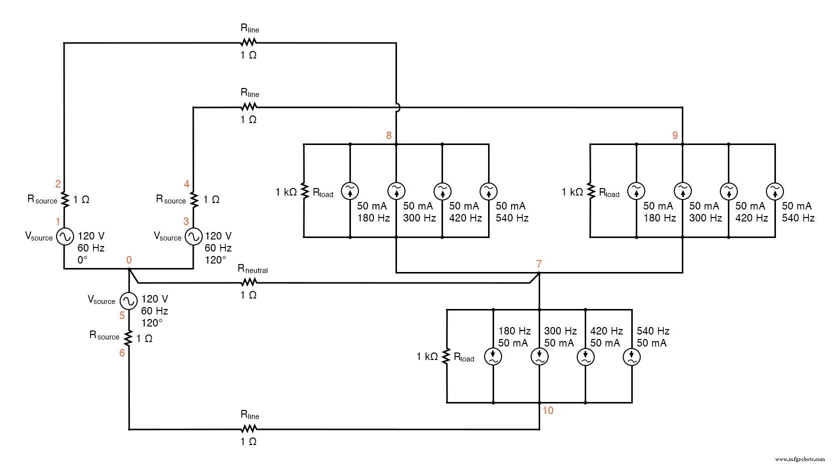 SPICE circuit: analysis of line and neutral currents in a balanced Y‑Y system.
Line Current Fourier Analysis
Fourier components of transient response v(2,8)
...
Neutral Current Fourier Analysis
Fourier components of transient response v(0,7)
...
The results confirm that triplen harmonics add constructively in the neutral, while fundamental currents cancel, leaving the neutral essentially free of 60 Hz flow.
5. Removing the Neutral Conductor
Eliminating the neutral shifts the balance: the Y‑center becomes a floating “hot” point, and triplen harmonic voltages (≈50 V) appear across each load phase and between the two Y‑centers. While this removes neutral currents, it introduces significant harmonic voltages on the phases.
6. Δ‑Y Source with Y‑Load
Connecting a Δ‑source to a Y‑load preserves balanced phase voltages but still allows triplen voltages across each load phase. The line currents remain dominated by non‑triplen harmonics.
7. Δ‑Δ Configuration
The Δ‑Δ system directly links source and load phases, eliminating the neutral and the associated triplen harmonic buildup. Harmonic currents generated by the load circulate within the Δ‑loop, never entering the line conductors or source windings. Consequently, line currents and load phase voltages remain largely sinusoidal, with THD below 1 % for the load voltage.
Key Takeaways
- Non‑linear devices produce harmonic currents whenever they draw non‑proportional current from a sinusoidal voltage.
- Symmetric distortion yields only odd harmonics; even harmonics are usually negligible.
- Triplen harmonics (3rd, 9th, 15th…) align in phase across 120‑deg‑shifted phases, causing additive neutral currents in Y‑Y systems.
- Δ‑Δ topology confines triplen currents to the load loop, preventing their spread to line conductors.
Related Worksheets
Industrial Technology
- Power Sources: AC and DC Explained
- Understanding Single‑Phase Power Systems: Efficiency, Safety, and Design
- Three‑Phase Power Systems: Fundamentals and Benefits
- Understanding Harmonic Phase Sequences in Three-Phase Power Systems
- Affordable Power‑Free Passive Cooling System Achieves 40°C Below Ambient
- Design Engineering for Energy‑Efficient Power Plant Generation Systems
- Advanced Harmonics Management: Part 2 – Effective Strategies & Measurements
- Types of Mechanical Power Transmission Systems: A Comprehensive Overview
- Understanding Harmonics: Impact on Power Systems and Mitigation Techniques
- UPS Circuit Design: Build Reliable Emergency Battery Backup Systems