


Advanced Motor Control Circuits: Latching, Stop, and Time‑Delay Techniques
The interlock contacts in the preceding motor control circuit function correctly; however, the motor remains energized only while each push‑button switch is actively pressed.
To allow the motor to continue running after the operator releases the controls, the circuit can be modified in two common ways: swap the momentary push‑buttons for toggle switches, or implement relay‑based latching that sustains power after a single actuation.
Industry practices favor the relay‑based latching method; let’s examine its implementation.
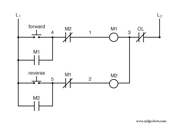
When the Forward push‑button is actuated, M1 energizes, closing the normally‑open auxiliary contact in parallel with that switch.
Upon release of the push‑button, the closed M1 auxiliary contact continues to energize the coil of M1, thereby latching the Forward circuit in the on state.
A similar sequence occurs when the Reverse push‑button is pressed. These parallel auxiliary contacts are often referred to as seal‑in contacts, where seal conveys the same concept as latch.
However, this design introduces a new challenge: stopping the motor. With the current configuration, the motor will run either forward or backward once the corresponding push‑button is pressed and will continue running as long as power is supplied.
To interrupt power to the motor contactors, we introduce a dedicated stop switch, labeled Stop.
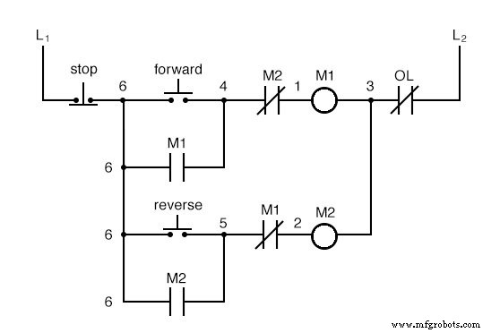
When either forward or reverse circuits are latched, the Stop push‑button can unlatched the circuit with a momentary actuation. Pressing Stop opens the corresponding circuit, de‑energizing the contactor and returning the seal‑in contact to its normal open state. Because Stop has normally‑closed contacts, it supplies power to the forward or reverse circuit when released.
So far, the system functions as intended. Next, we’ll address a practical consideration for motors driving high‑momentum loads such as large air fans.
After pressing the Stop button, the fan may continue to coast for several seconds. If the operator immediately presses the reverse push‑button while the fan is still coasting, the motor must fight the fan’s inertia, drawing excessive current and potentially shortening the life of the motor, drive mechanisms, and fan.
To prevent premature reverse startup, we add a time‑delay function to the motor control system.
We incorporate two time‑delay relay coils, one in parallel with each motor contactor coil.
The time‑delay relays provide a memory of the last motor direction and open the starting‑switch leg of the opposite rotation circuit for a specified interval, allowing the fan to come to rest.
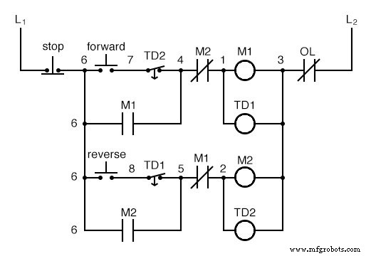
If the motor has been running forward, both M1 and TD1 are energized. The normally‑closed, timed‑closed contact of TD1 between wires 8 and 5 immediately opens when TD1 energizes. When the Stop button is pressed, TD1 holds the reverse push‑button circuit open for the delay period, preventing M2 from energizing. Once the delay expires, the contact closes and the reverse circuit can be activated if the reverse push‑button is pressed.
TD2 functions analogously, blocking the forward circuit after a reverse run until the specified delay elapses.
Because the TD relays’ contacts automatically open when their coils energize, the auxiliary contacts M1 and M2 used for interlocking become redundant and can be removed, simplifying the circuit.
Each time‑delay relay thus serves a dual purpose: it prevents the other contactor from energizing while the motor is running, and it delays energizing the same contactor until a prescribed interval after shutdown.
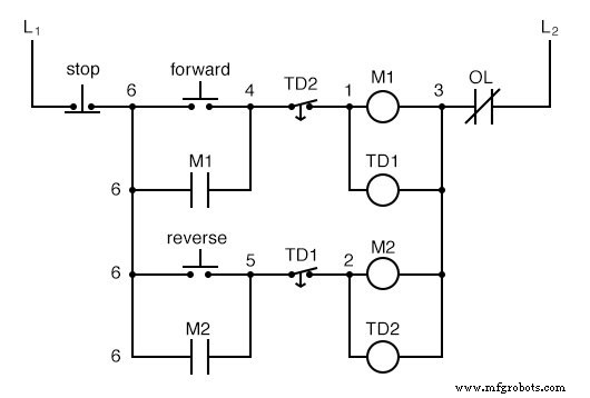
The resulting circuit is more streamlined than the previous example.
Review
- Motor contactor coils are commonly labeled M in ladder logic diagrams.
- Continuous motor operation with a momentary start switch is achievable by connecting a normally‑open seal‑in contact from the contactor in parallel with the start switch, allowing the contactor to maintain power to itself.
- Time‑delay relays are widely used in large motor control circuits to delay motor start or reversal until a defined period has elapsed after a preceding event.
Related Worksheets
- AC Motor Control Circuits Worksheet
- DC Motor Control Circuits Worksheet
- Electromechanical Relay Logic Worksheet
- Time‑Delay Electromechanical Relays Worksheet
Industrial Technology
- Permissive and Interlock Circuits in Industrial Control Systems
- Complementary NPN/PNP Audio Amplifier Circuit – Direct Coupling for Moderate Power
- Control Circuits: Fundamentals, Applications, and Best Practices
- Understanding Simple Series Circuits: Key Principles and Practical Examples
- Analyzing Complex RC Circuits Using Thevenin’s Theorem
- Fundamentals of AC Circuit Calculations: From Resistance to Kirchhoff’s Laws
- Series RC Circuit Analysis: Impedance, Phase Relationships, and SPICE Validation
- Parallel Resistor–Capacitor AC Circuits: Analysis, Impedance, and Ohm’s Law
- Impact of Resistance on Resonance in Series‑Parallel LC Circuits
- Inside the Manufacturing of Electronic Circuits