


Designing Fail‑Safe Control Systems for Safety and Reliability
Logic circuits—whether built from electromechanical relays or solid‑state gates—can be implemented in numerous ways to achieve the same functional outcome. While no single design is inherently “correct,” certain approaches offer superior safety, reliability, and maintainability.
In safety‑critical control systems, the design priority must be the protection of people, equipment, and processes. When multiple implementation options exist, the one that provides the greatest inherent safety should be selected.
Implementing Relay Logic in a Fire‑Alarm System
Consider a large laboratory or industrial building equipped with a fire‑alarm system that can be triggered by any of several latching switches scattered throughout the facility. The objective is to energize the alarm siren whenever any one switch is actuated.
The most straightforward relay logic would use normally‑open switch contacts wired in parallel—essentially an OR function across all inputs:
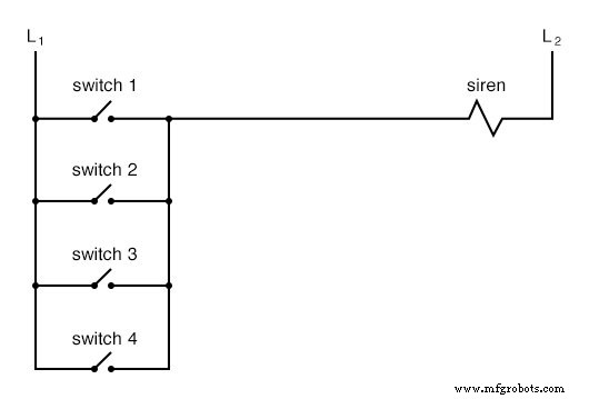
While this configuration is simple, it is vulnerable to the most common type of electrical failure: an open circuit. If, for example, the wire for Switch #2 fails open, the siren would not sound when that switch is activated—a dangerous condition that may go unnoticed until an emergency occurs.
To mitigate this risk, the circuit can be redesigned so that an open contact triggers the alarm. This requires normally‑closed switches arranged in series with a relay that energizes the siren when any switch is opened. The resulting circuit is:
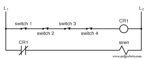
In this fail‑safe design, the relay coil (CR₁) remains energized when all switches are unactuated, keeping the relay contact (CR₁) open and preventing the siren from sounding. Activating any switch de‑energizes CR₁, closing the contact and sounding the alarm. A broken wire in the top rung also causes the relay to de‑energize, producing a false alarm that immediately signals a fault in the system.
Although this configuration is more complex than the original, it significantly improves safety by ensuring that a failure results in a detectable alarm rather than a silent malfunction.
Applying Fail‑Safe Principles Across Control Systems
Fail‑safe design is founded on the assumption that the most likely failure mode is an open circuit. By configuring the system so that such a failure defaults to the safest possible state, engineers can reduce risk. For example, an electrically‑actuated solenoid valve that supplies cooling water should be designed to remain open (allowing water flow) when de‑energized, because a loss of cooling can cause catastrophic equipment damage.
In power distribution, the choice of fail‑safe strategy becomes more nuanced. Protective relays controlling large circuit breakers often output a closed contact to initiate a trip. This approach means that an open failure in the control wiring will leave the breaker closed, potentially maintaining power to critical loads during a fault—a trade‑off accepted in many grid designs to avoid widespread outages.
These examples illustrate that fail‑safe design is not a one‑size‑fits‑all solution; it requires a clear understanding of the process, the most probable failure modes, and the safest response to those failures.
Standards such as IEC 61508 and ISO 13849 provide detailed guidelines for implementing fail‑safe systems in industrial and safety‑instrumented applications.
Review:
- The objective of fail‑safe design is to make a control system tolerant to the most common wiring or component failures.
- Because open circuits are statistically the most frequent failure, a fail‑safe system should default to its safest mode of operation when an open occurs.
Related Worksheets:
- High‑Reliability Circuits Worksheet
By systematically identifying likely failure modes and engineering systems to default to the safest condition, designers can create robust, trustworthy control solutions that protect people, assets, and processes.
Industrial Technology
- Common Pitfalls in New Systems: How to Avoid Early Failures
- Motion Detection Alarm System with Java & Reactive Blocks – Deploy on Raspberry Pi & Send SMS
- Expert Guide to Planning & Designing Power Distribution Systems
- Designing Energy Transmission Systems: Key Considerations & Constraints
- Expert Guide to Designing Gating Systems for Metal Casting
- SERENA: A Custom Arduino Mega 2560 Alarm System with TFT LCD Touchscreen
- Mastering Alarm Management: Build a Robust, Efficient System
- Build an Arduino Security & Alarm System – Step-by-Step Tutorial
- Designing Robust Waterproof Enclosures for Electronics: A Comprehensive Guide
- Optimizing High‑Speed PCB Design for Embedded Systems