


Programmable Logic Controllers (PLCs): Modern Digital Control for Industrial Systems
Before solid‑state logic circuits entered the scene, industrial control relied on electromechanical relays. While relays remain valuable for high‑current or high‑voltage applications, most on/off control functions are now handled by digital computers that can be programmed to perform a wide array of logical operations.
The History of Programmable Logic Controllers
In the late 1960s, Bedford Associates introduced the MODICON—an acronym for Modular Digital Controller. The MODICON quickly became the industry standard for dedicated control systems and eventually gave rise to the generic term Programmable Logic Controller (PLC). PLCs were designed to replace electromechanical relays with a solid‑state computer that could emulate the behavior of thousands of relay contacts via a stored program.
Ladder Logic and Programming PLCs
PLCs feature multiple input terminals that read high or low logic states from sensors and switches, and output terminals that drive lights, solenoids, contactors, or small motors. To make programming intuitive, the PLC language mirrors ladder logic diagrams—a format familiar to electricians and engineers who have worked with relay schematics.
Most PLCs operate on 120 VAC, matching the power levels of the relays they replace. Although some models support low‑level DC signals, 120 VAC remains the default. Signal connections and programming syntax vary slightly between manufacturers, but the underlying concepts are consistent, enabling a generic introduction here.
Below is a typical front‑view of a simple PLC. Two screw terminals supply 120 VAC (L1 and L2). Six screw terminals on the left provide input channels, each labeled X1–X6, with a common terminal tied to neutral.
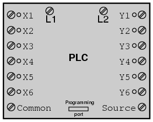
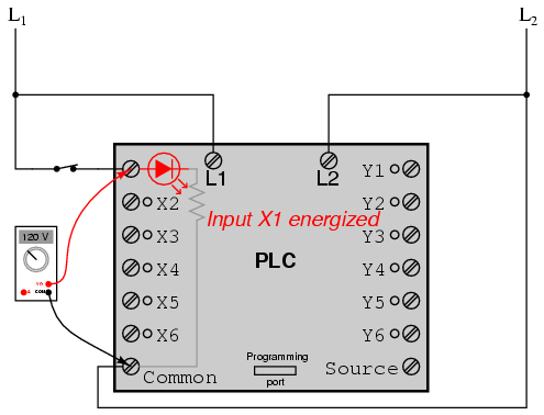
Internally, each input channel is connected to an opto‑isolator (LED + photo‑transistor). When 120 VAC is applied between an input terminal and the common, the LED lights, and a transistor inside the PLC interprets this as a high logic level. A front‑panel LED indicates that the input is energized.
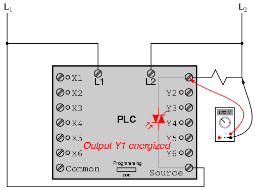
Output signals are generated by the PLC’s logic processor activating a switching device—transistor, TRIAC, or relay—connecting the “Source” terminal (usually tied to L1) to one of the Y‑labeled output terminals. A panel LED confirms when an output is energized.
Thus, a PLC can interface with real‑world devices while all logical relationships are defined inside the controller’s memory. The program—often displayed as a ladder diagram—dictates which outputs activate under which input conditions. The diagram’s contacts and coils are virtual; they exist only as program instructions, not physical components.
Control System Behavior
Because PLCs are programmable, changing system behavior requires only a software update, not hardware rewiring. For instance, a simple switch‑lamp circuit can be inverted by altering the ladder logic from normally‑open to normally‑closed contacts.
Consider a more complex scenario: energize a lamp only when at least two of three pushbuttons are pressed simultaneously. An electromechanical relay solution would need multiple relays and contacts, whereas a PLC can reuse a single input bit multiple times within the program, eliminating extra hardware.
Another common application is motor start‑stop control. A PLC can implement a latch (seal‑in) using an output contact as a virtual relay coil, keeping the motor energized after the start button is released. A stop button can break this latch to halt the motor.
Fail‑Safe Design in PLC‑Controlled Systems
Fail‑safe considerations are as critical for PLCs as for relay circuits. For example, a wiring failure that opens the stop input would normally cause a relay‑based motor control to remain on. By designing the PLC logic to treat the stop input as normally‑closed and the start input as normally‑open, the system automatically shuts down if the stop wiring fails.
PLCs also provide internal coils and contacts—essentially virtual relays—that can invert logic or provide additional safety functions without extra wiring.
Advanced PLC Functionality
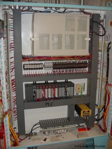
Beyond basic on/off control, PLCs can execute precise timing functions, drum sequencing, and other complex tasks with accuracy far superior to electromechanical relays. Many PLCs support far more than six inputs and outputs; for example, an Allen‑Bradley PLC can host modules with sixteen points each, allowing dozens of devices to be monitored and controlled from a single cabinet.
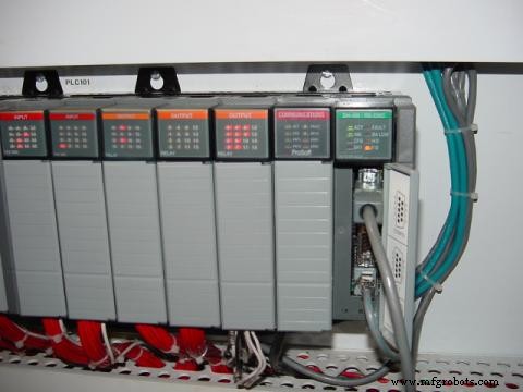
In a control cabinet, a PLC occupies minimal space compared to the relay array that would be required for equivalent functionality.
Remote Monitoring and Control of PLCs via Digital Networks
One advantage unique to PLCs is the ability to monitor and control processes remotely over digital computer networks. A PC can display real‑time process graphics—such as a liquid‑level schematic for a wastewater lift station—while the PLC manages the underlying control logic.
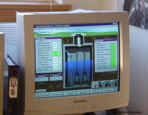
Remote connectivity enables operators to adjust setpoints, troubleshoot issues, and verify system performance from any location with network access.
Industrial Technology
- Integrated Circuits: Fundamentals of Digital Logic Gates
- Understanding Boolean Algebra: From Logic Foundations to Digital Circuits
- Combinational Logic Functions: Fundamentals & Practical Applications
- Exploring FPGAs: Applications, Benefits, and Getting Started with VHDL
- Essential PLC Strategies for Advanced Robot Cell Automation
- Understanding Programmable Logic Controllers: Key Facts for Industrial Success
- Mitsubishi Unveils Ultra‑Compact FX5UC Premium Micro PLC – Smallest, Most Powerful in FX Series
- Top 20 PLC Manufacturers: A Comprehensive Guide
- Advanced Ladder Logic: Master PLC Scanning Techniques
- Programmable Logic Controllers (PLCs): The Brain Behind Industrial Automation