


Understanding Simple Series Circuits: Key Principles and Practical Examples
In this guide we present the three foundational rules that govern series circuits, illustrated with clear examples and verified by computer simulation.
Core Principles of Series Circuits
- Current Consistency: The same current flows through every component because there is only one path.
- Resistance Addition: Total resistance equals the sum of individual resistances.
- Voltage Division: The supply voltage equals the sum of voltage drops across each element.
Illustrative Example: Three Resistors & One Battery
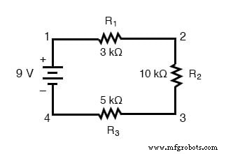
Consider a simple circuit with a 9‑V battery powering three resistors (3 kΩ, 10 kΩ, and 5 kΩ) in series, as shown below:
Applying Ohm’s Law
With a single source and a series arrangement, the current through each resistor is identical. However, Ohm’s Law (I = E/R) must be applied to each resistor using its own voltage drop and resistance. In a multi‑resistor setup, we first compute the equivalent resistance:
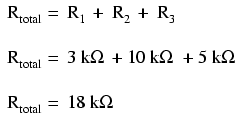
For the example: Rtotal = 3 kΩ + 10 kΩ + 5 kΩ = 18 kΩ.
With the total resistance known, the overall current is:
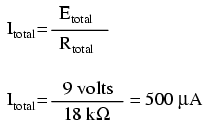
Result: I = 9 V / 18 kΩ = 0.5 mA (500 µA).
Determining Individual Voltage Drops
Using the established current, Ohm’s Law applied to each resistor gives:
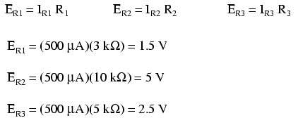
Verification: 1.5 V + 5 V + 2.5 V = 9 V, matching the supply.
Streamlined Analysis with the Table Method
The table method organizes all circuit parameters, ensuring correct application of Ohm’s Law within each column:
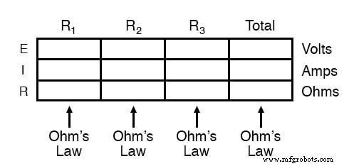
Step‑by‑step, we fill known values, compute the total resistance, derive total current, then back‑calculate each resistor’s voltage drop.
Verification via SPICE Simulation
To confirm our hand calculations, we employed SPICE—a standard circuit simulation tool. The netlist below describes the circuit:
series circuit
v1 1 0
r1 1 2 3k
r2 2 3 10k
r3 3 0 5k
.dc v1 9 9 1
.print dc v(1,2) v(2,3) v(3,0)
.end
Running this netlist yields:
| v1 | v(1,2) | v(2,3) | v(3,0) | i(v1) |
|---|---|---|---|---|
| 9.000E+00 | 1.500E+00 | 5.000E+00 | 2.500E+00 | -5.000E-04 |
The simulated voltage drops match the manual results, and the computed current is 0.5 mA (negative sign reflects SPICE’s current direction convention).
Key Takeaways
- All components in a series circuit carry the same current.
- Total resistance is the algebraic sum of individual resistances.
- Supply voltage equals the sum of individual voltage drops.
Further Practice
Test your understanding with these worksheets:
- Series DC Circuits Practice Worksheet with Answers
- Algebraic Equation Manipulation for Electric Circuits Worksheet
For quick calculations, use our Ohm’s Law Calculator in the Tools section.
Industrial Technology
- Building and Troubleshooting a Basic 6‑V Battery‑Lamp Circuit
- Key Rules for Series Circuits: Current, Resistance, and Voltage
- Advanced Motor Control Circuits: Latching, Stop, and Time‑Delay Techniques
- Complementary NPN/PNP Audio Amplifier Circuit – Direct Coupling for Moderate Power
- Understanding Series and Parallel Circuits: How They Work and Why They Matter
- Building Resistor Circuits: From Alligator Clips to PCBs
- Analyzing Complex RC Circuits Using Thevenin’s Theorem
- Fundamentals of AC Circuit Calculations: From Resistance to Kirchhoff’s Laws
- Series RC Circuit Analysis: Impedance, Phase Relationships, and SPICE Validation
- Series LC Resonance: Zero Impedance and Voltage Peaks Explained